 EN
EN

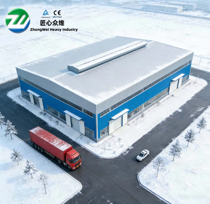
Why a Few Degrees Can Break a Frame’s Back
Steel rigid frames look massively strong standing upright, but their stability relies on a chain of bolted connections, each one cut and aligned to a specific angle. When a rafter to column connection lands a degree or two off the shop drawing, the bending moment does not disappear. It finds the path of least resistance, often the base plate, a flange brace, or a purlin cleat that was never meant to carry that load. Keeping the installation angles correct from the very first column plumb check is the difference between a frame that settles into its design geometry and one that fights itself for the life of the building.
Setting Anchor Bolts to the Right Tilt and Position
Everything starts with the anchor bolts cast into the foundation. A cluster of four bolts with a template plate seems foolproof until the concrete pour shifts the template by half an inch and tilts the bolt group by two degrees. The column base plate then sits cocked, and the erector faces a choice, either shim the gap and live with the eccentricity or cut the bolts and start over. The American Institute of Steel Construction (AISC) Steel Construction Manual allows a column plumb tolerance of 1:500, which translates to roughly a quarter-inch out of plumb for every 10 feet of height. Anchor bolt groups that exceed a 1:200 angular tilt before the column is even bolted down eat up most of that tolerance before any frame adjustments begin.
The Rafter-to-Column Moment Connection Angle
This is the joint that transfers bending stress from the rafter into the column. On a typical rigid frame, the end plate is shop-welded to the rafter at a precise bevel angle, usually matching the roof slope plus a half-degree of over-detail to allow for fabrication and erection tolerances. When the crane lifts the rafter into position and the bolts are drawn up, any gap between the end plates that exceeds AISC’s recommended snug-tight gap of roughly 1/16 inch signals an angle mismatch. Forcing the plates together with the bolts instead of rechecking the cut angle introduces residual stress that can initiate cracks at the weld toe years later, especially under cyclic wind loading.
| Frame Connection Point | Typical Design Angle | Common Field Error | Structural Consequence |
|---|---|---|---|
| Column base to foundation | 90 degrees to slab | 1 to 2 degree base plate tilt | Base moment eccentricity increases 15-20% |
| Rafter end plate to column | Roof slope angle (3:12 to 6:12) | 1.5 degree bevel mismatch | Bolt prying forces double under design load |
| Knee brace to column/rafter | 45 degrees nominal | 3 to 5 degree off-axis bolting | Brace buckling load drops 30%+ |
| Flange brace to purlin | 90 degrees to purlin web | 10 to 15 degree twist | Reduced lateral bracing stiffness by half |
A Cautionary Tale from a Steel Mill Expansion
An electric arc furnace building expansion in Alabama involved attaching a new crane bay to an existing rigid frame line. The erection crew set the first three new interior columns and bolted the rafters using a digital inclinometer for rough checks. One rafter-to-column connection ended up with a 2.3-degree discrepancy between the shop-cut bevel and the as-erected position because the column had drifted slightly out of plumb during the bolt-up sequence. Nobody caught it until the runway beam for the overhead crane was surveyed and found to be 3/8 inch out of parallel over 60 feet. The fix required loosening the entire moment connection, re-plumbing the column with two independent theodolite setups, and re-torquing every bolt in the sequence specified by the connection design. The lesson was that a single unchecked angle cascaded into crane rail misalignment, which could have caused wheel flange wear and derailment risk.
Bracing and the Illusion of Squareness
Knee braces and flange braces look simple, a short piece of angle iron with a couple of bolts. Their effectiveness drops off a cliff when the brace is bolted at an angle that deviates more than a few degrees from the intended load path. A brace intended to work in pure axial compression starts picking up bending moments the second the bolt holes are misaligned. The fix is not to drill the holes oversize and hope the washer bridges the gap. The correct approach is to match the brace to the frame after the main members are plumbed and squared, then drill the final hole locations in place. This takes more time on the front end but avoids a brace that looks fine in a photo and does almost nothing under load.
Checking Diagonal Lengths, Not Just Angles
A rigid frame bent is a giant triangle, or a series of triangles, and checking the internal angles with a digital level only tells half the story. Measuring the cross-diagonal distances between column base and rafter peak on both sides of the frame gives an immediate reality check. When both diagonals match within a 1/8 inch tolerance, the frame is square in plan and the angles are correct. When they differ by half an inch, something is out of plumb or twisted, regardless of what the inclinometer says at each joint. Field engineers who rely on this tape-measure check catch problems that a mis-calibrated digital tool would miss entirely.
Building Angle Accuracy into the Supply Chain
Angular precision starts long before the steel arrives on site. A manufacturing facility that uses CNC beam lines and robotic welding stations can hold bevel tolerances within half a degree, which leaves the erection crew a realistic window to work with. When the shop fabrication is accurate, the field crew can focus on alignment and plumbing instead of fighting to compensate for shop errors. Zhongwei runs its cutting and welding operations with precisely this philosophy, making sure that every end plate, base plate, and brace connection leaves the factory within the tight angular tolerances that a stable rigid frame demands. That factory-level discipline turns what is often a stressful correction process on site into a straightforward assembly sequence.
Table of Contents
- Why a Few Degrees Can Break a Frame’s Back
- Setting Anchor Bolts to the Right Tilt and Position
- The Rafter-to-Column Moment Connection Angle
- A Cautionary Tale from a Steel Mill Expansion
- Bracing and the Illusion of Squareness
- Checking Diagonal Lengths, Not Just Angles
- Building Angle Accuracy into the Supply Chain