— It is not enough to simply “drain the rainwater away”; the key is keeping the roof system controllable after primary drainage failure
Abstract
Steel-structure warehouses typically have large roof areas, long drainage paths, and lightweight roof systems. Once an internal gutter or roof drain becomes blocked during heavy rainfall, water loading can quickly shift from a building drainage issue into a structural issue. Many projects calculate only the downpipe diameter without evaluating gutter elevations, secondary overflow inlets, actual roof deflection, and primary-drainage failure scenarios within the same model. From the perspective of a dedicated design review, this article discusses drainage zoning for large-span steel warehouses, the relationship between primary drainage and secondary overflow, gutter deformation, and roof ponding stability. The objective is not to provide a universal rule of thumb such as “what pipe diameter is required per square meter,” but to establish a water-path logic that can be verified consistently during design, detailing, and site acceptance.
1. Why Steel-Structure Warehouses Are More Sensitive to Ponding Than Small Roofs
Lightweight steel roofs offer low self-weight, long spans, and fast construction, but these same characteristics make them more sensitive to continuously increasing water loads. Warehouse roofs are commonly formed by metal roof systems supported by purlins, steel beams, or trusses. Under normal conditions, rainwater follows the roof slope into internal gutters and is then discharged through roof drains and vertical downpipes. The problem is that rainfall is not a constant load, and drainage capacity is not a constant that can be assumed to remain effective forever.
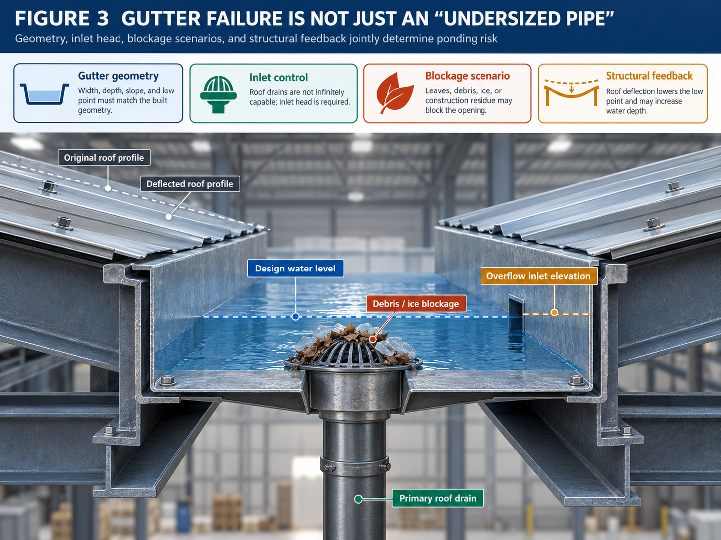
When roof drains are partially blocked by leaves, packaging film, construction debris, or localized ice and snow, the water level in the gutter rises. The higher water level increases the load on the gutter, purlins, and primary structure, causing deflection. That deflection further changes the actual low points of the roof, directing more water toward the already deflected areas. This feedback loop—“more water → greater deflection → more concentrated drainage”—is why ponding effects require separate attention.
Therefore, drainage design for a steel-structure warehouse must answer more than “Can the roof drain a normal design storm?” It must also answer: “If the primary drainage system fails, where will the water accumulate, how deep will it become, and will the structure still have adequate strength and stiffness?”
2. The Design Water Level Must Be Understood as Three Separate Components
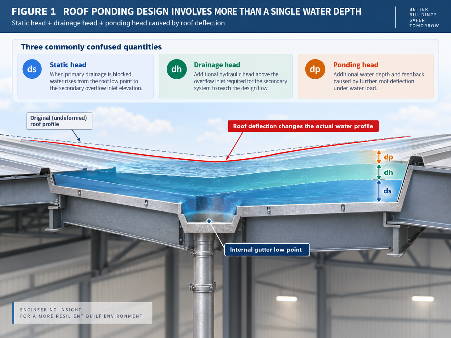
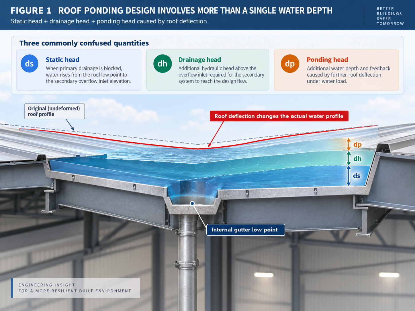
The 2024 International Building Code places further emphasis on the combined concept of static head, drainage head, and ponding head when expressing design rain loads. For engineering judgment, these three quantities should be understood separately rather than reducing roof ponding to an arbitrarily selected water depth.
The first component is static head. After the primary drainage system is blocked, this is the height by which the water surface rises from the roof low point to the secondary overflow inlet, and it is directly governed by the roof elevation and overflow elevation. The second component is drainage head. Even after water reaches the overflow inlet, the secondary drainage system may still require a certain hydraulic head above the inlet to achieve the design flow rate. The third component is ponding head. As the roof deforms under the water load, the actual low point drops further, changing both water depth and the contributing catchment area. This component cannot be determined from the undeformed roof geometry alone.
For long-span lightweight steel roofs, the third component is especially important. In 2024, AISC and the Steel Joist Institute jointly published Design Guide 40, Rain Loads and Ponding, dedicated to rain loads and ponding on steel roof systems. The guide also notes important updates in the 2022 edition of ASCE 7 regarding rain loads and ponding after roof deformation. From an engineering standpoint, this means drainage calculations and structural deflection cannot be treated as completely independent issues.
3. Define Drainage Zones First, Then Size the Gutters and Downpipes
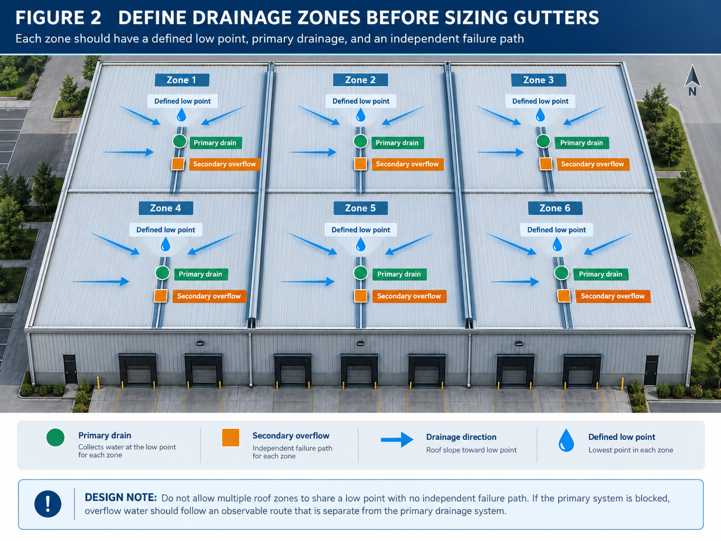
One of the most common design mistakes on large warehouse roofs is to determine several downpipe locations first and then work backward to decide how the roof should drain. A more reliable sequence is the opposite: first divide the roof into independent drainage zones based on ridges, slope directions, movement joints, gutter locations, and building length; identify the controlling low point and maximum catchment area for each zone; and only then arrange roof drains, downpipes, and overflow provisions.
Each drainage zone should have a clear “normal water path” and “failure water path.” The normal water path is roof sheeting → gutter → roof drain → downpipe. The failure water path describes how water is discharged safely through a secondary overflow opening, overflow pipe, or eave when the primary roof drain or primary drainage system is assumed to be unavailable. This failure path is particularly important for roofs surrounded by parapets, internal gutters, or high perimeter edges, because the water has no natural opportunity to flow over the roof edge.
In international engineering practice, both the IBC and the International Plumbing Code require secondary emergency drainage where roof-edge construction can cause water to be retained. The purpose of the secondary system is not to improve everyday drainage efficiency, but to provide an independent discharge path if the primary system fails. The two systems should not simply be combined into the same concealed downstream pipe, because a single blockage event could then disable both the primary drainage and the backup path.
4. Gutter Size Is More Than “Width × Depth”: Inlet Control and the Actual Low Point Also Matter
Gutter hydraulic capacity is often simplified to cross-sectional area, but actual drainage performance is also affected by longitudinal slope, local contractions, roof-drain inlet geometry, strainers, bends, vertical pipes, and outlet conditions. BS EN 12056-3:2000 is still listed by BSI as the current standard for gravity roof drainage. It provides hydraulic calculation methods for non-siphonic roof drainage systems and also sets performance requirements for siphonic systems.
For a steel-structure warehouse, gutter detailing should confirm at least four items. First, can the low point shown on the design drawings actually be achieved within fabrication and installation tolerances? Second, will gutter supports and structural deformation create a reverse slope? Third, how much inlet head does the roof drain require at the design flow rate? Fourth, is the secondary overflow inlet set so high that the structure would enter an unfavorable ponding condition before the overflow becomes active?
This is particularly important for long gutters with only a small nominal longitudinal slope. A few millimeters to more than ten millimeters of steel-beam deflection, support deviation, or local welding distortion may be enough to change the actual drainage direction. Detailing therefore should not stop at simply labeling a “gutter slope”; control elevations, support points, and allowable deflection should be checked together.
5. The Key to Secondary Overflow Is Not Merely Having It, but Its Elevation and Independence
Many projects show overflow openings on the drawings without verifying the relationship between the overflow inlet elevation and the structural design water level. An overflow opening that is too high may exist in form but allow ponding to reach a depth that the structure is not intended to carry before it becomes active. Likewise, a secondary system that shares a downstream pipe segment with the primary drainage system may be lost during the same blockage event.
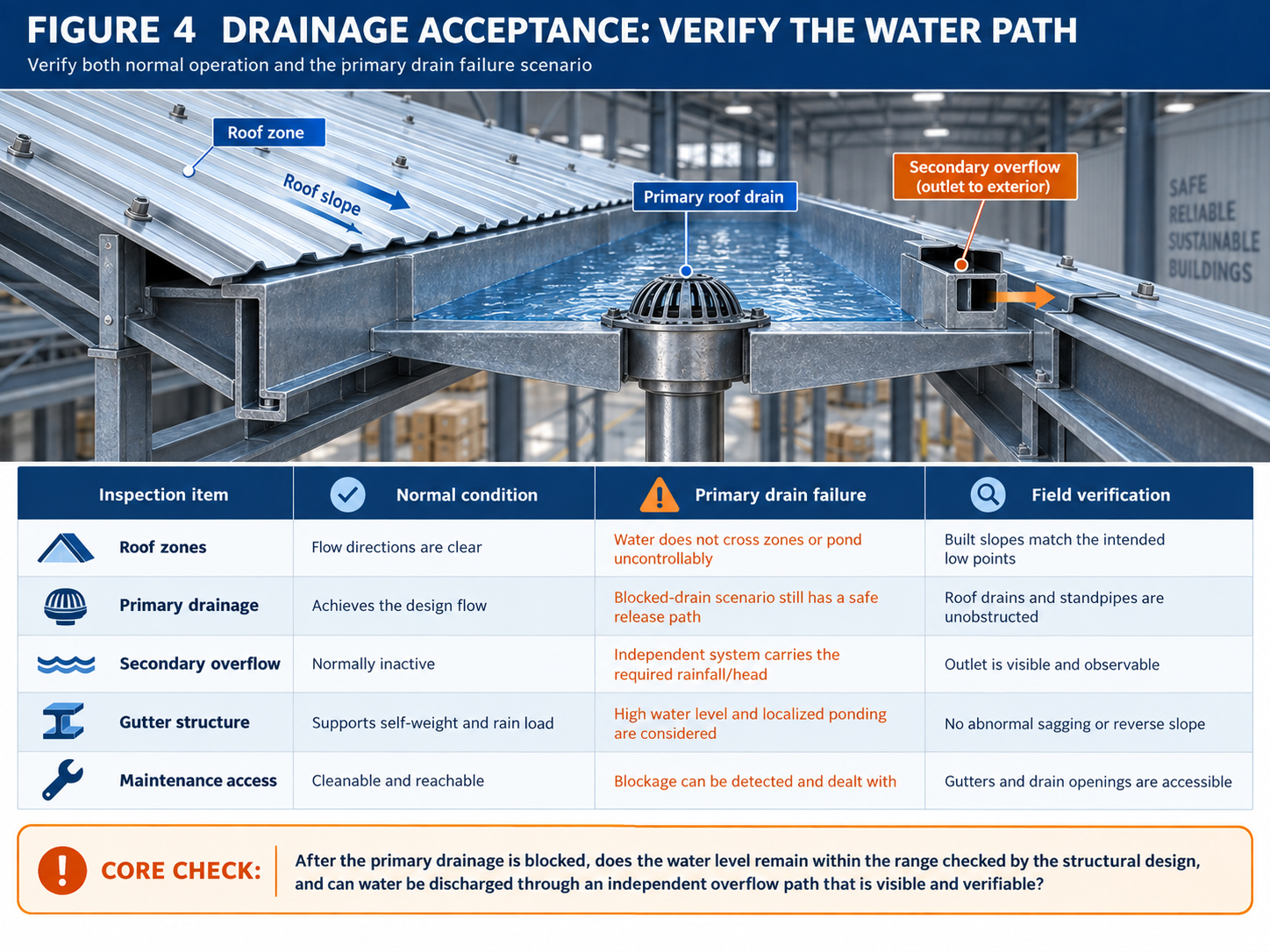
A more rational design approach is to first determine the maximum control water level permitted for the roof under a primary-drainage failure scenario, and then work backward to establish the overflow inlet elevation and discharge capacity. Overflow water should preferably discharge at a location that maintenance personnel can easily observe, because activation of the secondary system is itself an alarm signal that “the primary drainage system is abnormal.”
Public provisions in the 2021 IPC explicitly require the secondary roof drainage system to terminate separately from the primary system and to discharge above grade at a location that is normally observable by building occupants or maintenance personnel. The secondary system is sized using the same design rainfall intensity as the primary system. Each project should follow the version currently adopted by the local jurisdiction, but the engineering principle is broadly applicable: a backup system must be genuinely independent, and its activation should be visible.
6. The Roof Structure Must Account for the “More Water, More Ponding” Feedback
For structural engineers, the key question is not whether there is water in the gutter, but whether the ponding load still converges to a stable condition after the roof deforms. The current AISC 360 specification requires roof systems that may be subject to ponding to be checked by structural analysis for adequate strength and stability, unless the roof construction itself prevents water accumulation. AISC/SJI Design Guide 40 provides a more systematic method for analyzing rain loads and ponding.
In real projects, ponding sensitivity is typically related to span, roof slope, secondary-beam or purlin stiffness, primary-beam stiffness, and the locations of drainage low points. A small roof with adequate slope and free drainage at the perimeter may have very low ponding risk. By contrast, a warehouse with long spans, low roof slope, and concentrated drainage through internal gutters may develop significant additional water depth because of insufficient stiffness, even when the steel members have ample strength reserve.
Design review therefore cannot stop at checking whether the “rain load combination” has been selected. It must also determine whether the analysis model reasonably represents the actual drainage boundaries of the roof. Structural deflection, gutter support conditions, and overflow elevations should form a consistent closed loop. If the model calculates water depth on the undeformed roof but the actual roof would deflect significantly under that water depth, the ponding feedback should be investigated further.
7. Siphonic Drainage Is Not a Universal Solution—and Where It Is Appropriate, Coordination Is Even More Critical
Large-span warehouses sometimes use siphonic roof drainage to reduce the number of downpipes. Siphonic systems achieve high drainage capacity through full-bore flow, but they are more sensitive to roof-drain performance, pipe-diameter combinations, hydraulic balancing, air conditions, and installation quality. They should not be modified casually using ordinary gravity-drainage experience.
BS EN 12056-3 includes performance requirements for siphonic roof drainage. In the United Kingdom, a new edition of BS 8490 was published in 2025, providing guidance on design parameters, installation, verification, and maintenance of siphonic roof drainage systems. Where a siphonic system is used, early coordination between the steel-structure and MEP disciplines becomes even more important: roof drains require stable mounting bases; loads and vibration from pipe supports must have clearly defined load paths; gutter water depth must match siphonic priming conditions; and a safe drainage route must still be provided for abnormal primary-system conditions.
For fabrication and construction teams, one of the most dangerous practices with siphonic systems is making arbitrary site changes to pipe diameters, elevations, bend arrangements, or roof-drain locations. Any of these changes may disrupt the hydraulic balance of the system.
8. Design Deliverables Should Allow the Site Team to “Verify the Water Path”
High-quality dedicated drainage drawings should provide more than the quantity and diameter of downpipes. They should make clear which dimensions are control dimensions. At a minimum, the drawings should identify roof drainage zones, catchment area of each zone, primary roof-drain locations, gutter control elevations, secondary overflow inlet elevations, overflow directions, whether the primary and secondary systems are independent, and the control water level used in structural calculations.
After installation, acceptance should also be upgraded from “Has it been installed?” to “Does the failure scenario still work?” Checks may include whether the actual roof low points match the drawings, whether gutters contain reverse slopes, whether insulation, sealant, or edge trims reduce the effective roof-drain opening, whether overflow openings are concealed by decorative covers, whether downpipes have been reduced in diameter on site, and whether secondary drainage outlets are genuinely visible.
For long-term operation and maintenance, gutters and roof drains must be accessible for cleaning. Where trees, dust, or windblown packaging materials are present around a warehouse, maintenance frequency should be increased. Designing for a single blockage event does not mean that long-term neglect is acceptable.
Conclusion
Roof drainage for steel-structure warehouses is, in essence, a dedicated engineering issue involving the interaction of building drainage, hydraulic calculations, and deformation of lightweight steel structures. Calculating downpipe diameter alone cannot answer whether the roof remains safe after the primary drainage system becomes blocked; structural rain-load verification alone cannot ensure that real water will follow the intended discharge path.
A more reliable engineering method starts by defining drainage zones, then establishing primary drainage, secondary overflow, and the allowable structural water level, and finally checking the actual gutter elevations, roof-drain head requirements, and roof deflection within the same engineering logic. The objective is not to make the drainage system more complicated, but to ensure that during extreme rainfall or localized blockage, water still follows a path anticipated by the designer rather than finding a new low point on the roof that was never included in the calculations.
Table 1 Four Control Levels for Dedicated Roof Drainage Design in Steel-Structure Warehouses
Control level |
Question to answer |
Typical failure mode |
Hydrologic input |
Are the design rainfall intensity and catchment area clearly defined? |
The same empirical drainage rate is reused in different regions |
Hydraulic system |
Do gutters, roof drains, pipes, and overflow provisions satisfy the required flow and head? |
No problem in light rain, but gutters overflow during heavy storms |
Structural response |
Does the system remain stable after the water level rises and the roof deforms? |
The low point continues to deflect and the ponded area expands |
Failure & maintenance |
After the primary system is blocked, is there an independent, observable discharge path? |
The backup and primary systems become blocked together without being noticed |
References and Standards
1. ASCE/SEI 7-22: Minimum Design Loads and Associated Criteria for Buildings and Other Structures. One of the current U.S. structural loading standards; its rain-load provisions should be considered together with ponding effects after roof deformation.
2. 2024 International Building Code (IBC): Chapter 16 includes updated design rain-load concepts. Public explanatory material states that design rain loads are based on the combination of static head, drainage head, and ponding head; Chapter 15 requires roof drainage to be coordinated with structural rain-load requirements.
3. International Plumbing Code (IPC): Chapter 11, Storm Drainage, includes requirements for primary roof drainage, siphonic drainage, and secondary emergency drainage. The version adopted by the project jurisdiction should govern.
4. BS EN 12056-3:2000: Gravity drainage systems inside buildings - Roof drainage, layout and calculation. BSI still lists it as Current as of 2026. It is used for hydraulic calculation of non-siphonic roof drainage and also includes performance requirements for siphonic systems.
5. BS 8490:2025: Siphonic roof drainage systems - Guide. A current BSI guide covering siphonic drainage design parameters, installation, verification, and maintenance.
6. AISC Design Guide 40:2024: Rain Loads and Ponding. Jointly published by AISC and the Steel Joist Institute, it specifically addresses rain loads, ponding behavior, analysis, and design for structural steel and steel-joist roof systems.
7. ANSI/AISC 360-22: Specification for Structural Steel Buildings. Used for strength and stability design of structural steel systems; where a roof may be subject to ponding, corresponding structural analysis is required unless the roof construction prevents water accumulation.
#SteelStructureWarehouse #InternalGutter #RoofDrainage #SecondaryOverflow #RainLoad #PondingStability #SiphonicDrainage
 EN
EN