A compliant hole diameter does not guarantee field fit-up; the key is continuous control of datums, hole groups, and member alignment
Abstract
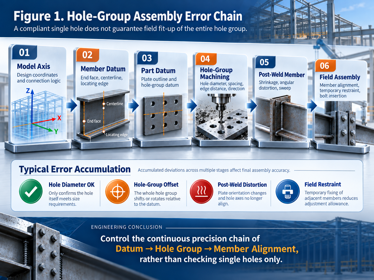
In the fabrication and erection of steel structure warehouses, “bolt holes do not line up” is often simply blamed on inaccurate drilling. In practice, however, the causes of difficult bolt insertion on site are usually more complex. The diameter of each hole in a connection plate may be fully compliant, while the hole group as a whole may shift or rotate because of datum transfer, cumulative hole-spacing error, welding shrinkage of the plate, member sweep, connection-plate angular deviation, or temporary restraints during erection. From the perspective of fabrication control, this article discusses how hole-group coordinates should be established and inspected, how machining methods should be selected, and how the limits of field correction should be judged when misaligned holes are found. It does not cover the complete steel-structure project process. Instead, it focuses on one specific issue: how to ensure that hole positions shown on the drawings ultimately become connections that can be bolted smoothly on site while still satisfying the required structural performance.
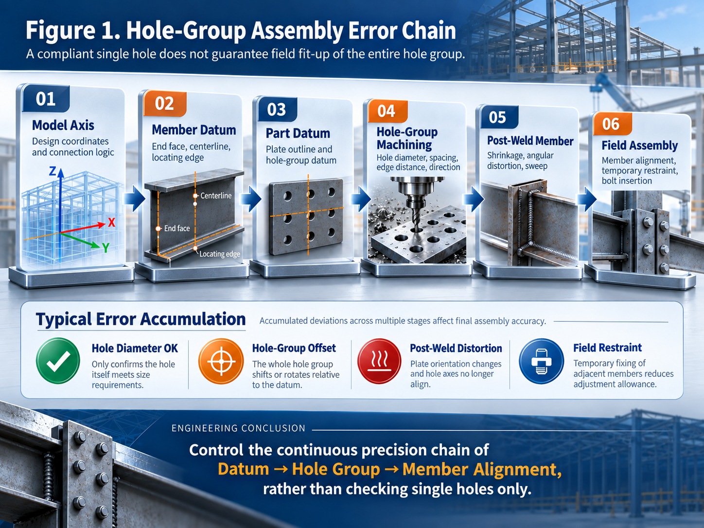
1. When Holes “Do Not Line Up” on Site, the Problem Is Often Not a Single Hole
Bolted connections are discrete connections. A typical beam-to-column joint may contain only a few groups of holes, but those holes must simultaneously satisfy relative positional relationships across two or even three different members. What field erection really requires is not merely that “each hole diameter is within tolerance,” but that, once the connected members are positioned, the axes of all holes requiring bolts can coincide within the permitted adjustment range.
This means that hole-group precision must be understood as a system. Suppose all ten holes in a connection plate pass gauge inspection. If the entire hole group is shifted 3 mm relative to the plate edge, or if the connection plate rotates by 2–3 mm at the hole line after being welded to a beam web, every individual hole may still pass inspection, yet the hole group may already be difficult to bolt through simultaneously on site. Conversely, if a small burr on one hole edge obstructs bolt insertion, that alone does not prove that the hole-group coordinates are incorrect.
Therefore, the first step in fabrication quality control is to distinguish among “hole-size problems,” “hole-group coordinate problems,” and “member-geometry problems.” The inspection methods, repair methods, and effects on structural performance are completely different for these three categories.
2. Establishing a Unified Datum Is More Important Than Repeatedly Measuring Hole Spacing
One of the most common sources of systematic error in hole-group fabrication is the use of different datums in different processes. The detailing model may use the member centerline as the datum; plate cutting may use the lower-left corner of the plate; and assembly may use the cut end face or one edge of the web. If the relationships among these datums are not explicitly defined, every individual process can appear “accurate” while the final accumulated deviation still becomes significant.
For steel warehouse members manufactured in batches, at least three levels of datums should be clearly defined in detailing and fabrication documents. The first level is the member control datum, such as a column centerline, beam-end control face, or web centerline. The second level is the connection-plate part datum, such as a locating edge, centerline, or reference hole. The third level is the internal hole-group datum, such as the first-hole position, hole-spacing direction, and hole-group symmetry axis.
This is especially important for mirrored parts, left-hand and right-hand connection plates, and repetitive members in multi-bay buildings. Errors in which the “outline is the same but the hole-group direction is reversed” must be prevented. Digital equipment can improve repeatability, but it does not automatically eliminate an incorrect datum. Incorrect NC data will simply reproduce the same error more consistently across an entire batch. First-article verification therefore remains an essential process.
3. Hole-Group Inspection Should Evolve from Single-Hole Checks to “Coordinate-Relationship Inspection”
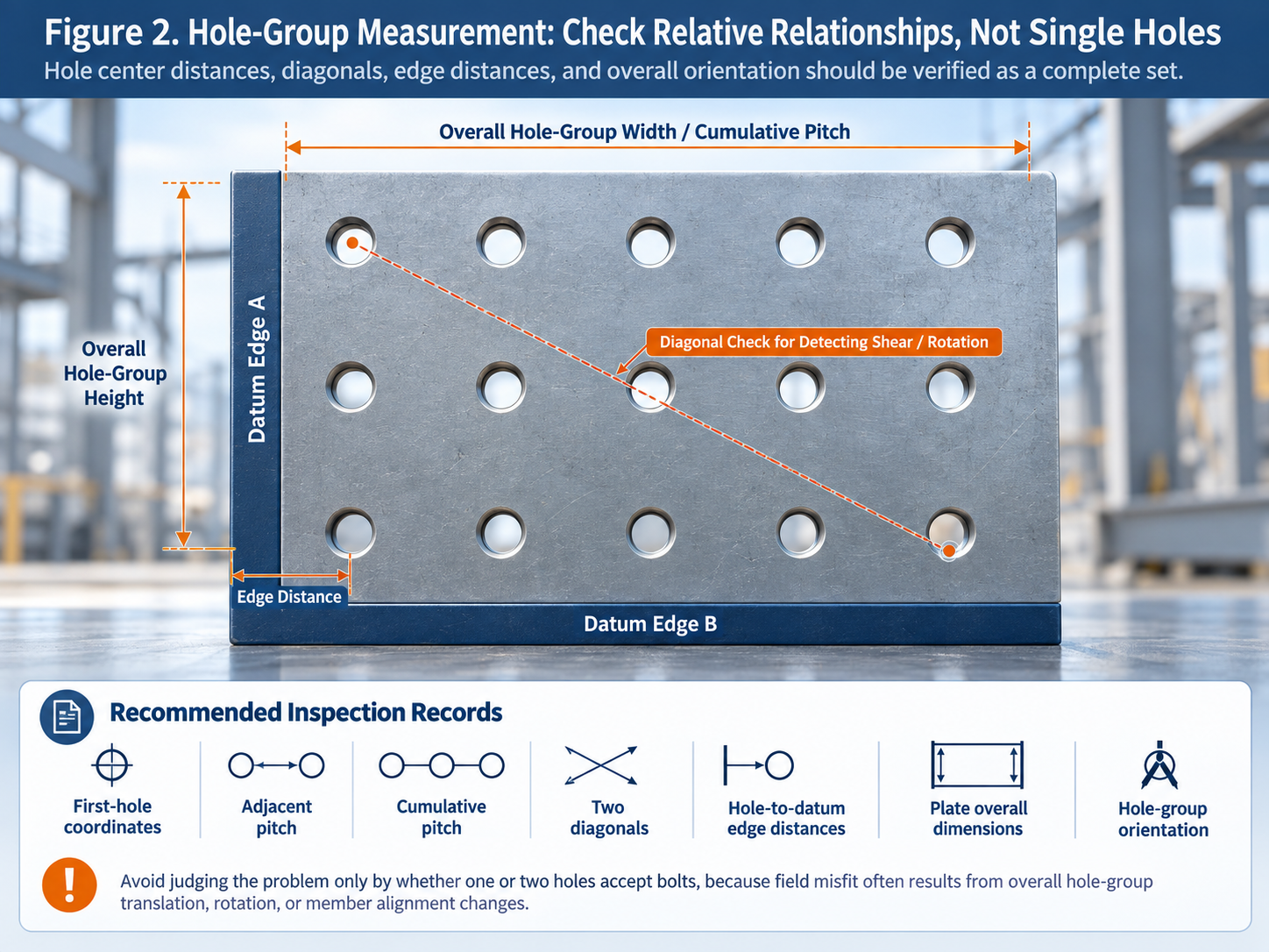
Inspection of a connection plate should not be limited to hole diameter and adjacent hole spacing. A more effective approach is to use a set of mutually checking dimensions to determine whether the hole group has shifted or rotated as a whole. These dimensions include the distance from the first hole to two datum edges, adjacent hole spacing, cumulative hole spacing, total hole-group width and height, the two diagonals, and the overall dimensions of the connection plate.
The two diagonals are particularly valuable. If horizontal and vertical hole spacing is basically correct but the two diagonals differ noticeably, the hole group or plate may have undergone shear deformation or rotation, or the plate outline may not be square. If all inter-hole spacings are correct but the distance from the first hole to the datum edge is abnormal, an overall translation of the hole group is more likely. If the data are correct during plate machining but change after welding, attention should shift to welding shrinkage and assembly positioning rather than continued investigation of the drilling equipment.
For multi-hole connections such as beam end plates, column splice plates, and bracing gusset plates, inspection should also include the perpendicularity, flatness, and angle of the connection plate relative to the member axis. Field bolt insertion is a three-dimensional problem; correct two-dimensional hole coordinates are only one part of it.
4. CNC Drilling, Thermal Cutting, and Punching Have Different Suitable Application Limits
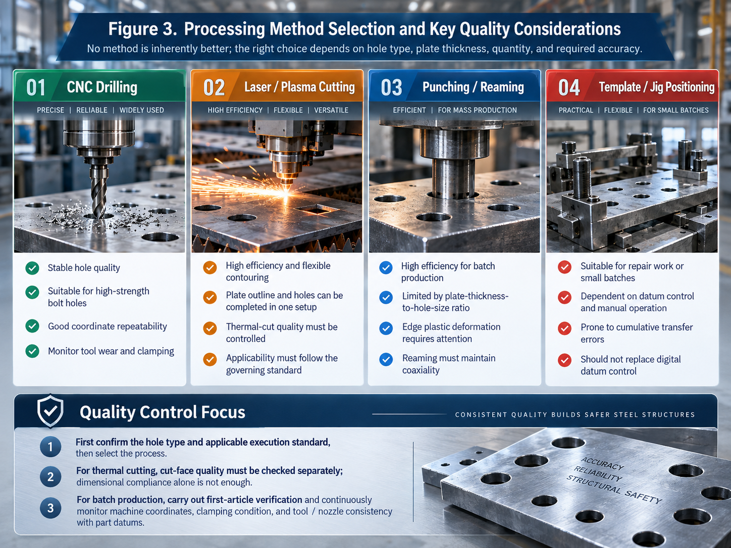
In modern steel fabrication plants, connection holes may be produced by CNC drilling, laser or plasma thermal cutting, punching followed by reaming, and other methods. The machining method should not be selected on speed alone. Plate thickness, hole diameter, hole type, production quantity, execution standard, and the importance of the connection must also be considered.
CNC drilling offers relatively stable hole-wall quality and dimensional repeatability, making it especially suitable for high-strength bolted connections and hole groups that require higher coaxial accuracy. However, drilling can still suffer from drill-bit wear, spindle runout, insufficient clamping, and plate warping that causes coordinate drift. A correct coordinate displayed by the machine does not necessarily mean the actual hole center is correct, so first-article inspection and in-process sampling cannot be omitted.
Thermal cutting can produce the plate outline and holes in a single operation and offers high efficiency, but hole geometry also involves cut-face perpendicularity, dross, roughness, and heat effects. ISO 9013 covers geometrical product specifications and quality tolerances for thermal cutting and was amended in 2024. If a project document references this standard, inspection cannot be limited to hole diameter while ignoring the quality class of the cut surface. Whether a specific bolt hole may be produced by thermal cutting must follow the execution standard, design documents, and procurement technical requirements applicable to the project.
Punching is efficient for batch production under certain plate-thickness and hole-diameter conditions, but plastic deformation at the hole edge, burrs, and the coaxial accuracy of subsequent reaming must be controlled. No machining method is inherently “more advanced.” Professional fabrication means selecting the method according to connection performance and the applicable execution standard.
5. Hole Positions Must Be Reassessed After Welding: The Connection Plate Has Become Part of the Member
Many field hole-misalignment problems do not originate during part machining; they appear after the connection plate has been welded to a beam or column. End-plate welding, corbel welding, and concentrated welds around stiffeners all introduce shrinkage. If restraint during assembly is unreasonable, the connection plate may undergo slight rotation or warping, while the member itself may develop sweep or twist.
Therefore, for critical hole groups, retaining only the “part machining inspection record” is not sufficient. After member welding and straightening are complete and the member has naturally cooled, the critical connection surfaces should be remeasured. This does not mean rechecking every dimension. Instead, the reinspection should focus on control items that indicate field fit-up capability, such as the distance from the beam end face to the first row of holes, the distance from the hole-group center to the web centerline, end-plate perpendicularity, and the positional relationship of the hole groups at both ends relative to the member axis.
ISO 13920:2023 specifies general tolerance classes for linear dimensions, angles, shape, and position in welded constructions. However, the particular class to be applied should be defined by the drawings, contract, or project execution documents. For structural-steel execution, EN 1090-2 and AISC 303 likewise emphasize that fabrication and erection tolerances should be coordinated with the contract documents and structural function. In other words, one generic tolerance class should not be used to cover every critical connection.
6. The Real Risk in Batch Production Is Being “Consistently Wrong”
An occasional deviation in a single part is usually easy to detect. In batch production, systematic errors are more dangerous. For example, if the first-hole coordinate in an NC program is entered 2 mm incorrectly, the machine can repeat that same error consistently on the next one hundred connection plates. Similarly, if a stop block in an assembly fixture is displaced, every beam end plate may develop an angular error in the same direction.
For this reason, batch-fabricated members need the concept of an “error trend,” rather than relying only on a final pass/fail judgment. After first-article approval, critical dimensions should be sampled periodically. If consecutive data points drift in the same direction, tools, fixtures, locating blocks, machine coordinates, and material flatness should be checked before the allowable deviation is exceeded. The value of statistical records is that they reveal the trend while the product is still compliant.
This method is especially effective for highly repetitive portal-frame warehouse projects. Large quantities of column-bracing gusset plates, beam-to-column end plates, purlin cleats, and similar parts are involved. If systematic hole-group misalignment is not discovered until erection, the rework cost is far higher than correcting the process in the workshop.
Table 1 Quick Diagnostic Matrix for Hole-Group Mismatch
Field Observation |
Priority Checks |
Conclusion That Should Not Be Drawn Directly |
Difficulty inserting a bolt through one hole |
Burrs, coating buildup, local obstruction |
Do not immediately conclude that the hole-group coordinates are wrong |
An entire hole group shifts in the same direction |
First-hole datum, NC coordinates, assembly fixture |
Do not enlarge holes one by one and continue erection |
Diagonal holes become progressively harder to align |
Hole-group rotation, end-plate angle, member twist |
Do not rely only on adjacent hole-spacing measurements |
The same problem repeats across members from one batch |
Program, machine, fixture, or common datum |
Do not treat it as a random field error |
7. Handling Misaligned Holes on Site: Understand the Connection Mechanism Before Deciding Whether It Can Be “Repaired”
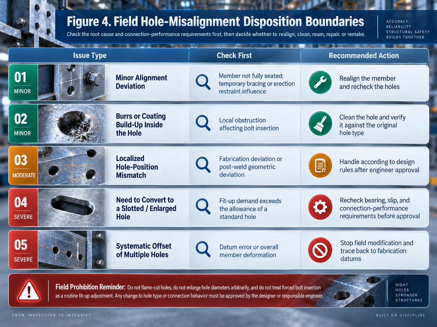
When holes do not line up on site, the least professional response is to immediately flame-cut the holes or enlarge them arbitrarily. Standard holes, oversized holes, short-slotted holes, and long-slotted holes in high-strength bolted connections are not geometrically interchangeable; each corresponds to different connection design conditions. The bolted-connection provisions of AISC 360 and the RCSC Specification for high-strength bolted joints distinguish among hole types and their permitted uses.
Field action should therefore begin by excluding the simplest causes: whether the member is fully seated, whether temporary bracing has pulled the member out of alignment, whether burrs, coating buildup, or weld spatter obstruct the holes, and whether an unintended gap exists between the faying surfaces. If the problem is caused by member alignment, the correct alignment should be restored first. If it is caused by a local obstruction, the obstruction should be removed without changing the designed hole type.
When reaming, changing a hole to a slot, or otherwise altering the original connection geometry is genuinely required, the treatment should be confirmed by the designer or responsible engineer. Enlarging or changing a hole may affect bearing resistance, net section, slip behavior, edge distance, and washer or plate requirements. If multiple holes show systematic displacement, individual holes should not simply be “modified until the bolt fits.” Instead, the member datums and overall geometry should be traced back so that a systematic fabrication error is not disguised as minor field repair.
8. Special Quality-Control Recommendation: Make Hole-Group Data Traceable
For steel structure warehouse projects with large quantities of repetitive members and a fast erection sequence, hole-group quality is best supported by traceable digital records. It is not necessary to create a complex coordinate-measuring-machine report for every plate, but critical members should at least be traceable to the member mark, part number, machining equipment or workstation, first-article approval result, post-weld reinspection data, and records of any nonconformance disposition.
A three-stage inspection approach is recommended. After the part is completed, check hole diameter, hole-group coordinates, and plate geometry. After member welding, check the orientation of the connection surface and the position of critical hole groups relative to the member axis. Before dispatch, use member-level dimensional checks to confirm fit-up capability. For joints where the design permits preassembly or shop trial assembly, the trial assembly result can be used as verification rather than treating trial assembly as a rework step used only after problems have appeared.
The value of this targeted control is not to create more inspection forms, but to make it possible to quickly identify at which datum-transfer stage an error occurred. What a fabricator truly needs to control is not just one hole, but the continuous precision chain from detailing data to successful bolt insertion on site.
Conclusion
Connection accuracy in a steel structure warehouse may appear to be a fabrication detail, but it directly affects erection efficiency, joint performance, and overall project delivery quality. Compliance of individual hole dimensions is only the most basic level of acceptance. A more reliable approach is to establish hole-group coordinates around unified datums and use first-article verification, process-trend monitoring, and post-weld member reinspection to convert part-level accuracy into member fit-up accuracy.
Reference Codes and Standards
1. BS EN 1090-2:2018+A1:2024: Execution of steel structures and aluminium structures — Technical requirements for steel structures. A systematic reference for structural-steel fabrication, assembly, geometrical tolerances, inspection, and execution requirements.
2. ISO 9013:2017 + Amd 1:2024: Thermal cutting — Classification of thermal cuts — Geometrical product specification and quality tolerances. Used for the classification of geometrical quality and tolerances for flame, plasma, and laser thermal cutting.
3. ISO 13920:2023: Welding — General tolerances for welded constructions — Dimensions for lengths and angles, shape and position. Used for general tolerance classification covering linear dimensions, angles, shape, and position of welded constructions.
4. ANSI/AISC 303-22: Code of Standard Practice for Steel Buildings and Bridges. Used as a reference for general structural-steel fabrication and erection practices, including fabrication and erection tolerances.
5. ANSI/AISC 360-22: Specification for Structural Steel Buildings. Used for structural-steel connection design requirements, including bolted-hole types.
6. RCSC Specification 2020: Specification for Structural Joints Using High-Strength Bolts. Used for hole types, installation, and connection behavior in structural joints using high-strength bolts, and serves as an important basis for judging whether field hole enlargement or a change in hole type is acceptable.
#SteelStructureWarehouse #ConnectionPlate #HoleGroupAccuracy #CNCDrilling #HighStrengthBolts #FabricationTolerances #FieldFitUp
 EN
EN