How loads are transferred inside the container matters—not merely how many pieces will fit. |
For exported steel-structure warehouses and industrial buildings, long, slender beams and columns are often shipped in segments inside freight containers. Packing plans tend to focus on length, piece count, and space utilization. Yet the factors that actually govern transport risks are frequently the less visible load paths. A steel beam that meets every dimensional requirement in the fabrication shop may not retain its geometry after a voyage involving ship motions, road braking, and container handling.
When discussing export packing methods for fabricated steelwork, Shenyang Zhongwei Heavy Industry Steel Structure Engineering Co., Ltd. advocates assessing “loading space” and “load restraint” separately. The former determines whether members will pass through the container doors and whether weight limits are met; the latter examines how forces are transferred through the members, timber dunnage, blocking, lashings, and container structure. This article focuses exclusively on in-container support and securing of long, slender members, without expanding into fabrication, erection, or overall project management.
Export container packing begins with an accurate schedule of each member’s external dimensions. In addition to maximum length, width, and height, projecting end plates, stiffeners, brackets, and connection lugs may determine whether the member can pass through the doorway. Door openings, internal clearances, and usable loading space on site are not interchangeable concepts; the maneuvering clearance needed by handling equipment, dunnage thickness, and protective layers all take up room. ISO 668:2020 and its 2022 amendment address the classification, dimensions, and ratings of Series 1 freight containers, but the internal dimensions of a particular container type still have to be verified against the relevant specifications and the actual unit.
A more serious trap is assuming that “payload capacity remains available on paper.” The container’s gross mass, allowable payload, individual piece weights, and loaded center of gravity must be assessed together. Even if the combined weight of a batch of beams is below the container’s payload limit, a small contact area may not safely support that weight. Geometric fit and structural suitability should be reviewed on separate checklists.
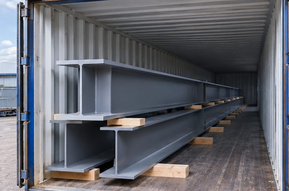
Long, slender steel beams are not infinitely rigid cargo. Excessive support spacing may lead to additional bending at midspan during transport; excessive end overhangs may subject local joints or end plates to repeated loads under vibration. Conversely, adding dunnage indiscriminately does not necessarily improve safety. When blocks are of unequal height, an intended multi-point support arrangement may become contact at only a few high spots, introducing unexpected torsion or local indentation.
Support locations should follow member geometry and the intended load path, not equal intervals along the container. For welded H-sections, support blocks should preferably be placed where compression can be transferred reliably without causing local buckling of vulnerable plates; where necessary, the locations should be coordinated with web stiffeners. For tapered beams, differences in section depth also need consideration so that gaps are not improvised away with loose scraps of timber.
With multi-tier stacking, the essential requirement is a clear vertical load path between upper and lower support positions. If the weight of an upper member is transferred to the lower member through a free flange edge or an unstable block, coating damage may occur first, followed by local bending. The aim of a sound stacking plan is not to maximize the number of tiers, but to make the contact location at every tier identifiable, verifiable, and stable.
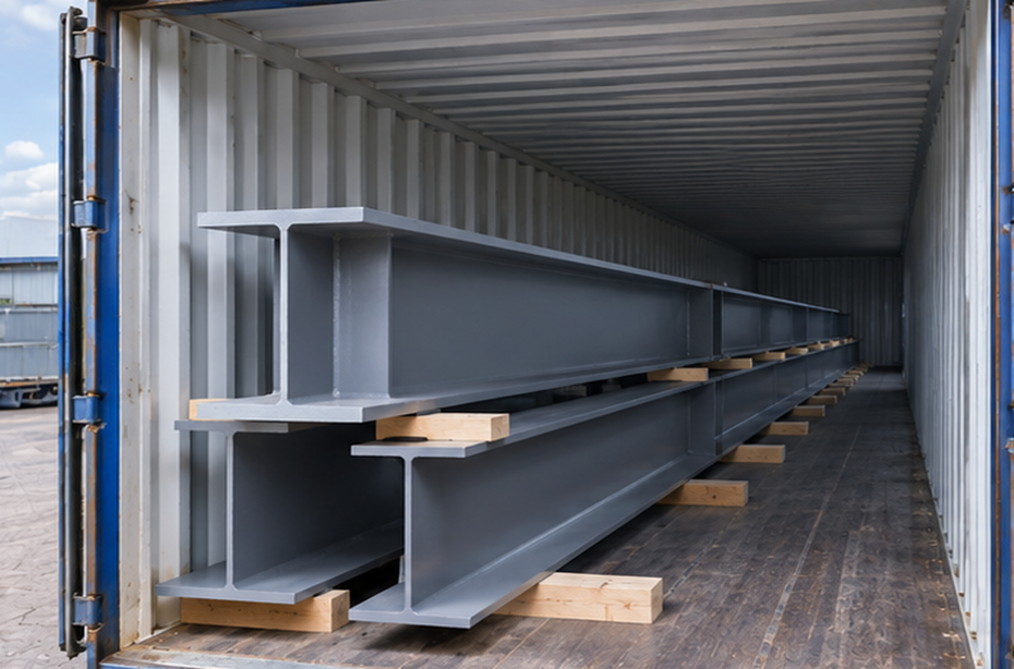
A packing plan must distinguish between “the member can withstand the load” and “the container can withstand the load.” Plate corners, narrow-edged steel shims, or undersized timber pads can concentrate several tonnes of cargo weight into a small bearing area. Even if the beam itself remains undamaged, the container floor may become indented or locally damaged, or support points may settle during transit, altering the lashing pretension originally assumed in the design.
The IMO/ILO/UNECE Code of Practice for Packing of Cargo Transport Units (CTU Code) treats cargo stowage, weight distribution, and securing inside a cargo transport unit as core elements of safe packing. It is non-mandatory international operational guidance and does not replace applicable local regulations or carrier-specific requirements. [1] ISO 1496-1:2013 and its 2024 amendment address the specifications and testing of general-purpose freight containers, but they cannot be taken as proof that a particular local floor-loading arrangement has been verified.
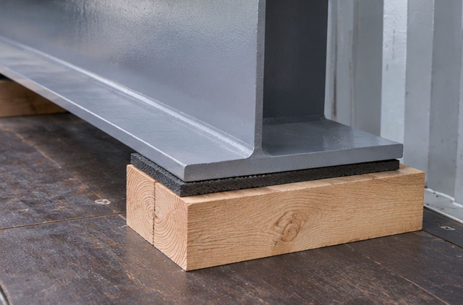
In engineering practice, load-spreading members of suitable length, width, and stiffness can distribute concentrated forces to appropriate load-bearing areas of the container. The bending resistance and stability of those spreaders must also be checked. Increasing the apparent surface area of timber blocks alone is not a completed verification: actual load transfer also depends on effective contact, timber condition, and floor construction. For heavy steelwork, permissible concentrated loads and related restrictions should be confirmed with the carrier or container operator.
Steel beams that appear stable while stationary in a workshop may experience inertia forces in different directions during emergency road braking, cornering, rail impacts, and vessel rolling. No exaggerated, single acceleration value is needed to make the point: once the direction of loading changes, supports that mainly carried dead weight may also be required to resist transverse shear, sliding, and local uplift.
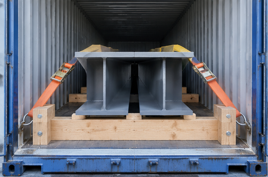
Blocking is intended to limit foreseeable movement, while lashings provide the designed restraint forces. The two should not be treated as one vague instruction to “tie it down tightly.” Longitudinal restraint may require end blocking against sliding, while lateral restraint must address sideways movement and overturning of grouped beams. For bundles with a high center of gravity, a single top-over strap may not develop a sufficient stabilizing moment. Whether multiple members may be treated as one cargo unit depends on reliable internal contact and interlocking within the bundle.
The force path of every securing device—from one anchorage to another—must also be reviewed. Without suitable edge protectors, webbing can be cut or abraded by sharp beam edges; lashing angles different from those assumed in the design change the effective restraint components; and the capacity of timber blocking attached to the floor only with unverified nails is difficult to substantiate. The drawings should identify permitted contact points, edges requiring protection, and anchorage points with confirmed allowable capacities.
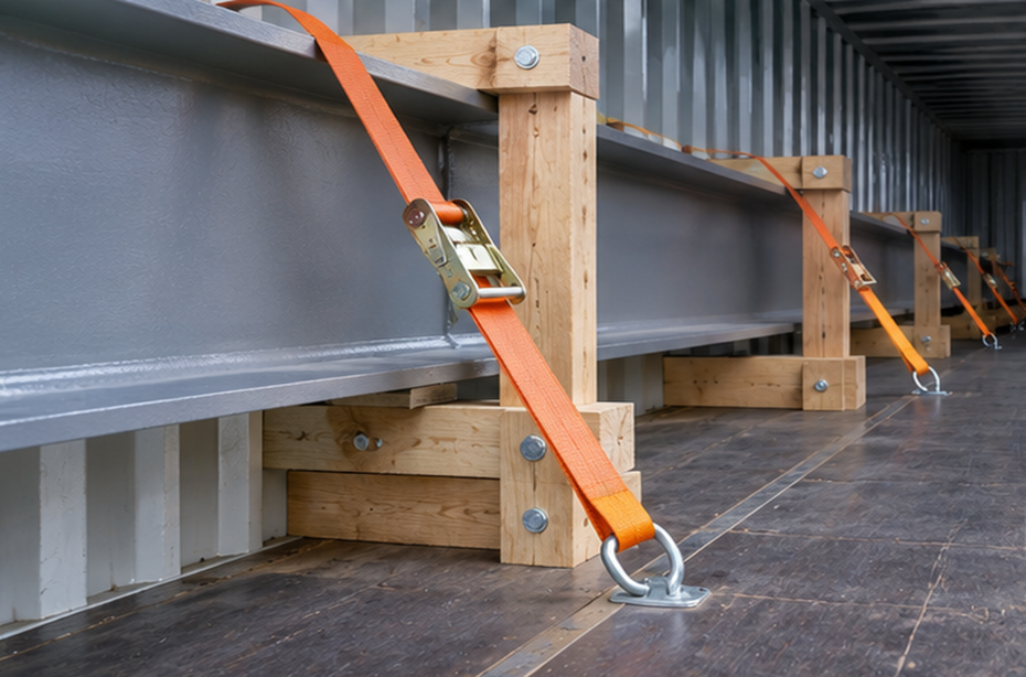
A complete restraint system is only as strong as its actual weakest link. A high-rated webbing strap cannot be credited with its nominal capacity when it is attached to a container lashing ring of unknown strength or transfers force through insufficiently stiff timber members. When multiple lashings work together, their working angles, differences in pretension, and load sharing must be checked; simply adding the rated values shown on product labels is not valid.
Friction can help prevent sliding, but the coefficient of friction is not a constant to be entered arbitrarily. Steel coating condition, surface moisture, pad material, contamination, and transport vibration all affect contact behavior. Where a design relies on anti-slip material, it should use substantiated performance data and defined conditions of application. Uncertain contact surfaces should be treated conservatively, with friction never serving as the sole line of defense.
One important distinction: ISO 3874:2017 mainly covers the handling and securing of Series 1 freight containers themselves, whether loaded or empty. It should not be used directly as a standard for checking the lashing capacity of steel beams inside a container. [4] Proper securing of the container aboard a ship does not prove that the cargo inside it is properly secured. These are two separate safety boundaries often confused in international transport.
To protect finished coatings, some packing arrangements place thick soft material between the member and its supports, effectively leaving the cargo “floating” on a cushioning layer. Although this may reduce short-term rubbing, it can introduce compression, creep, and loss of lashing pretension. The thickness, hardness, friction characteristics, and long-term compressive behavior of protective materials must be evaluated together with the support and securing arrangements.
A better approach is generally to give protective separation and structural support distinct functions: use sufficiently stable pads at designated bearing locations, and add corner protectors, sleeves, or separation layers of controlled thickness at sharp edges and coating-sensitive contact points. Soft packaging should not be allowed to carry unverified primary loads, nor should securing devices bear directly against vulnerable plates, coated corners, or the edges of precision-machined holes.
Closed containers experience changes in temperature and humidity, so packaging should also avoid trapped water and prolonged moisture retention. Corrosion protection is outside the scope of this article, but one point matters: if localized scuffing appears after transport, the incident should not be assessed solely by deciding to touch up the paint. Member geometry, impressions left by supports, and alignment of connection holes should also be checked.
I prefer to regard a packing record as a “verifiable statement of load paths,” not merely a few photographs showing that the cargo was placed inside the container. At a minimum, the record should identify each member and its weight; the locations and specifications of support pads; stacking relationships; forms of blocking; lashing routes; the basis for anchor-point selection; and the verified total weight and actual center of gravity of the loaded unit. For non-standard cargo groups, approved plans, necessary calculations, and records of on-site adjustments should also be retained.
Photographic evidence also needs technical focus. A single overall photograph taken through the doors cannot establish whether the supports deep inside the container are correctly positioned. It is more useful to document critical locations after installing the dunnage, after placing the first tier, after completing tier-by-tier lashing, and before closing the doors, with photographs traceable to member identification numbers. Then, even if the destination port reports a scratched or displaced beam, its original support and restraint conditions can be reconstructed.
If the actual container type, available internal anchorage points, or load distribution changes, site personnel should not improvise changes to the original plan based on experience alone. Engineers need to reconfirm the support arrangements, weight distribution, and restraint paths, modifying the packing method or selecting a more appropriate cargo transport unit if necessary. For overlength, overwidth, or overweight members, open-top containers, flat racks, and breakbulk shipping must each be assessed against their own boundary conditions; a plan for a standard dry freight container must not be copied mechanically.
The challenge in exporting steel structures is not to fill every centimeter of available space. It is to ensure that the members remain geometrically fit for installation after repeated handling and exposure to different transport conditions. Engineers should first be able to answer where supports belong, how loads are transmitted, how the container floor bears them, and how cargo movement is restrained.
For Shenyang Zhongwei Heavy Industry Steel Structure Engineering Co., Ltd., the value of discussing transport engineering is not to offer a fixed template for every beam type and shipping route. It is to treat each container loading as a distinct cargo-securing case. Packing arrangements should be verified by qualified or appropriately competent personnel based on the actual steel members, container, transport route, and carrier requirements. Only then can space utilization be improved without trading away cargo condition or delivery reliability.
[1] IMO / ILO / UNECE, Code of Practice for Packing of Cargo Transport Units (CTU Code), 2014. Non-mandatory international guidance on cargo packing.
[2] ISO 668:2020, Series 1 freight containers — Classification, dimensions and ratings; Amendment 1:2022.
[3] ISO 1496-1:2013, Series 1 freight containers — Specification and testing — Part 1: General cargo containers for general purposes; Amendment 2:2024.
[4] ISO 3874:2017, Series 1 freight containers — Handling and securing. This standard concerns the handling and securing of the container itself.
Leave your project requirements and get exclusive solutions for free!
E-mail: [email protected]
#SteelStructureExport #SteelBeamContainerLoading #SteelMemberLashing #CargoSecuring #LongSteelMemberTransport
 EN