— How Wind Loads Find a New Load Path After Wall Girts Are Interrupted
Abstract
In the design of steel structure warehouses, large overhead doors, sliding doors, or logistics door openings are often treated simply as architectural “opening dimensions”: the structural engineer provides the clear width and height, and the door supplier then installs its equipment to suit the opening. From a structural perspective, however, an opening several metres or even more than ten metres wide can directly interrupt multiple wall girts, sag rods, and even wall bracing, thereby changing the originally continuous load path of the building envelope. The key issue requiring dedicated engineering judgment is therefore not merely whether “two posts should be added at the sides of the opening,” but how the end reactions of the interrupted members bypass the opening, what loads are carried by the header and jamb posts, whether local members may twist under wind suction, and whether structural deformation remains within the allowable limits of the door tracks and sealing system. Focusing exclusively on large industrial door openings in steel structure warehouses, this article discusses load rerouting, perimeter-frame stiffness, wall-girt termination, construction interfaces, and acceptance logic with reference to ASCE/SEI 7-22, ANSI/AISC 360-22, ANSI/SDI AISI S100-24, ANSI/AISC 303-22, EN 1090-2:2018+A1:2024, and other applicable standards.
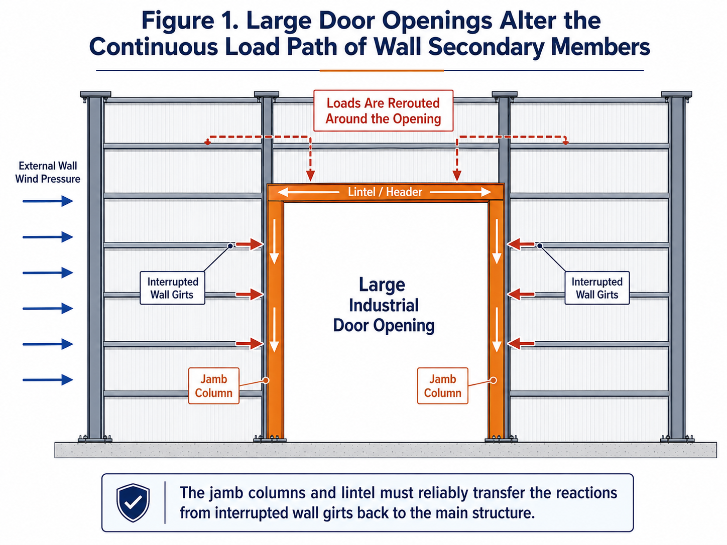
In a typical steel structure warehouse, wind pressure on profiled steel sheets or sandwich panels is transferred to the wall girts and then from the girts to rigid-frame columns, gable columns, or the wall bracing system. As long as the wall girts remain continuous, the load path is relatively clear. Once a large door opening is introduced, however, multiple wall girts must terminate at both sides of the opening. Each terminated girt then develops an end reaction that must be transferred into a new supporting element. If the design drawings show only jamb posts without clearly defining how the girt ends connect to those posts, how the jamb posts are restrained about their weak axis, or how the header coordinates the reactions from both sides, then the fact that “all the members appear to be present” does not mean that the load path has actually been closed.
This is the fundamental difference between a large industrial door opening and an ordinary window opening. Small window openings can often be resolved with short local girts or light perimeter framing. Industrial door openings, by contrast, frequently cut across several girt elevations, while the clear height of the opening may approach the eave level, leaving only limited structural depth for the header. The closer the door opening is to a gable end, a braced bay, or a building corner, the more complex the boundary conditions become. The proper design sequence is therefore to mark on the elevation every wall girt, sag rod, knee brace, and bracing member interrupted by the opening, and then assign a new load destination to each one. This should be done before selecting an “experience-based” jamb-post section and trying to complete the connection details afterwards.
The design input for the region around a large door opening normally comes from wall wind pressure. ASCE/SEI 7-22 provides a systematic framework for determining wind pressures on Components and Cladding (C&C); international projects may instead be designed in accordance with the locally adopted Eurocode, AS/NZS standards, or other wind-loading standards. One of the most common engineering errors is to take a wall design pressure, multiply it by the entire door-opening area, and apply the resulting force directly to a single jamb post.
A more rational approach is to establish tributary areas in accordance with the actual envelope panelization and wall-girt spans. The engineer should identify which girts support the remaining wall area above the door, calculate the end reaction from each girt, determine whether the narrow wall strips beside the door act directly on the jamb posts, and check whether the area above the header lies within a higher wind-suction zone. The load ultimately transferred to the jamb posts and header should be the combined result of these member reactions, rather than an undivided total surface load. For cold-formed C- or Z-shaped wall girts, ANSI/SDI AISI S100-24 applies to strength and stability design. Where hot-rolled H-sections, hollow structural sections, or welded members are used as the door perimeter frame, they should be checked in accordance with the project’s applicable primary structural steel design standard.
In some warehouse projects, the jamb post is initially intended only to provide an installation surface for door tracks, seals, and door hardware, so a relatively light section is selected. Once all wall girts terminate at the opening and connect into that post, however, its role changes. In addition to supporting door accessories, it receives horizontal reactions from multiple levels of wall girts and may also be subjected to torsion caused by connection eccentricity. If the opening is near the end of the building, the jamb post may also fall within a zone of high local wind suction.
Accordingly, the jamb post should be evaluated at a minimum for strength, overall stability, weak-axis bending, torsion, and service-stage deformation. In warehouses with tall openings, a common result is that the strong-axis utilization ratio is low while weak-axis lateral displacement is excessive. If the girt connections are concentrated on one side of the section, torsion caused by a mismatch between the shear centre and the load line must also be considered. Simply increasing section depth to improve strong-axis stiffness may not resolve the weak-axis or torsional problem; it may instead increase eccentricity at the door installation surface. The orientation of the jamb-post section, the location of the girt connections, and the door-track mounting surface should therefore be coordinated during the detailing stage rather than treated as separate decisions.
The header is often misunderstood as merely “a beam above the door.” In reality, when the height of the opening interrupts multiple wall girts, the header usually performs two functions. First, it directly supports the short wall girts or envelope edge members above the opening. Second, it redistributes local reactions from the jamb posts back into the adjacent primary structure. When the door is wide and the remaining wall above it is relatively high, the header may be subjected simultaneously to horizontal bending, vertical self-weight, local torsion, and connection eccentricity.
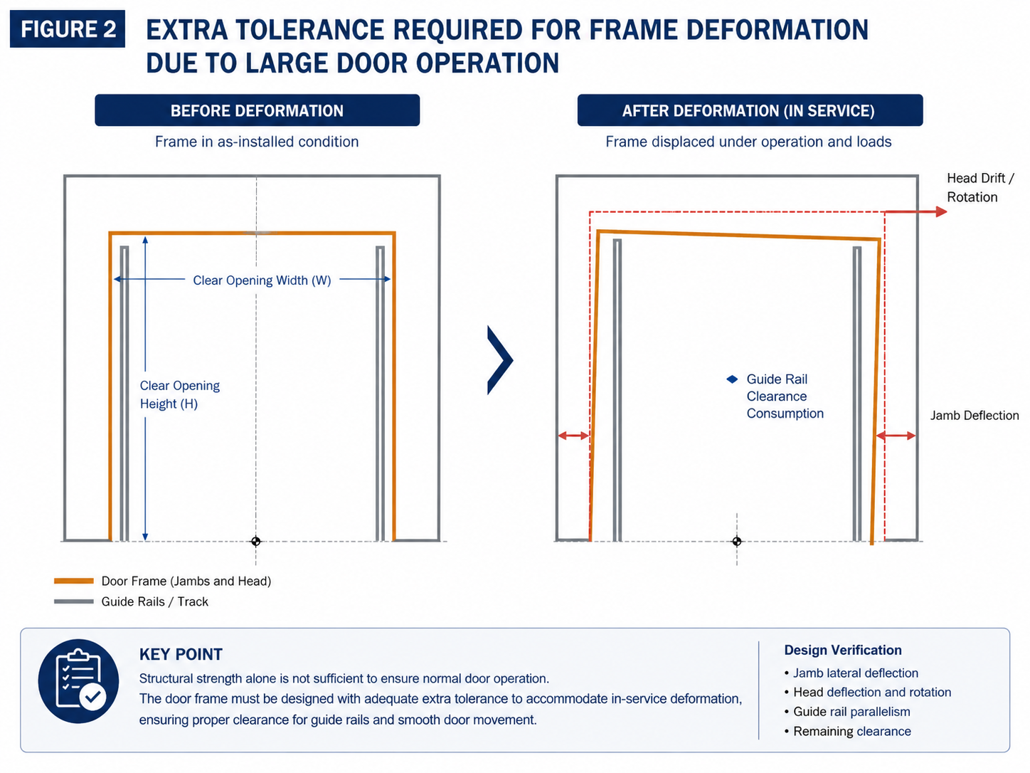
More importantly, header deflection directly affects the upper door track, roller shaft, or sealing arrangement. The deflection limit permitted by the structural design standard is not automatically equivalent to the installation tolerance permitted by the industrial door equipment. Different door types and different manufacturers may specify different limits for opening diagonals, track parallelism, header levelness, and operating clearance. A single “universal L/xxx” limit should therefore not be applied to every industrial door. The design documents should require the door-equipment supplier to provide allowable deformation and installation tolerances, after which the structural engineer should review the header and jamb posts for serviceability against those equipment-specific limits.
In dedicated door-opening design, the most important question is not whether the connection detail looks elaborate, but whether the end reaction from each wall girt has a clearly defined receiving member. Typical arrangements include connecting girts directly to jamb-post brackets, providing a continuous angle or connection plate along the jamb post to support multiple girt levels, or forming a local frame with the header and jamb posts and then transferring the reactions from that frame to the primary structure. None of these solutions is inherently superior. The critical requirement is that the load model represented by the connection matches the assumptions made in the structural calculation.
Where the wall girts are thin-walled cold-formed members, checks should also include local bearing at the end, web crippling or buckling, hole edge distance, and eccentricity in screw or bolt groups. Even when the jamb posts are hot-rolled sections, local deformation caused by girt end plates concentrated on one side of a flange or web should not be overlooked. A common site practice is to continuously weld an angle along the jamb post as a “universal connection strip.” Although convenient to fabricate, such a detail is not automatically reliable if the welds, local bending of the angle, and torsional response of the jamb post have not been verified.
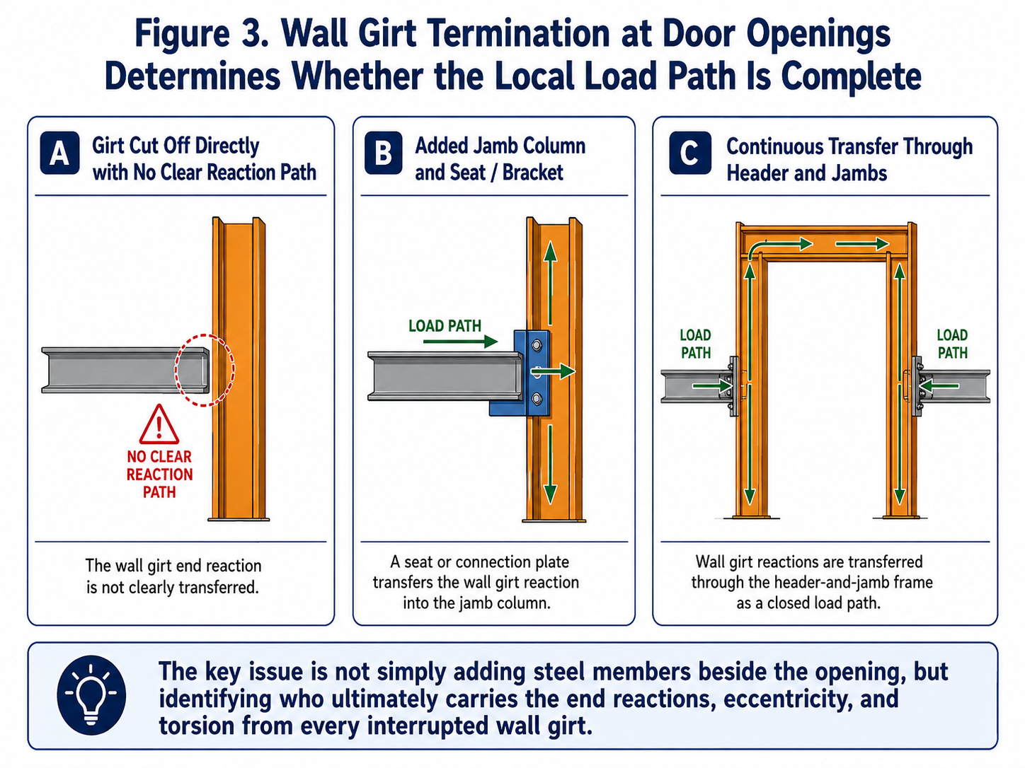
Large door openings are especially prone to conflict with wall cross-bracing, girt sag rods, knee braces, and MEP services. The most dangerous condition is not a deliberate, engineered deletion of bracing during design, but an unreviewed change during detailing or construction in which a diagonal brace is moved, shortened, or removed to clear the door opening without creating a replacement lateral load path.
If the opening lies within an originally braced bay, the bracing arrangement should be redesigned at the level of the global structural analysis, or an alternative system capable of resisting the relevant horizontal action should be provided. The door perimeter frame may contribute to the building’s lateral system only if it has been explicitly designed as a lateral-load-resisting frame; the presence of “more steel around the opening” does not mean it can be assumed to replace wall bracing. In portal-frame warehouses, the location of wall bracing is also related to longitudinal wind loads, crane braking forces, and construction-stage stability. Any adjustment caused by the door opening must therefore remain consistent with the overall structural model.
Many after-sales problems involving large industrial doors are not caused by yielding of steel members or failure of connections. Instead, the door may exhibit operational problems such as track friction, sticking panels, local separation of seals, misalignment of locks, or a marked increase in operating noise. The cause may be only a few millimetres to slightly more than ten millimetres of deformation in a jamb post or header. Such movement may not trigger a structural strength limit state, but it can already be unacceptable for door equipment that requires comparatively high installation precision.
For this reason, a dedicated door-opening design should establish at least two separate verification tracks. The first is structural safety, including strength, stability, and connection resistance. The second is serviceability, including relative displacement of the jamb posts, header deflection, change in opening diagonals, and rotation or twist of the installation surfaces. Serviceability limits should preferentially be based on explicit requirements from the door-equipment manufacturer and checked against the governing load cases from the structural analysis. If the supplier has not yet been selected, the design documents can state “submission of allowable door deformation and installation tolerances” as a technical interface requirement rather than allowing the structural discipline to assume an unconfirmed value on its own.
ANSI/AISC 303-22 emphasizes clear interfaces among design, fabrication, and erection parties with respect to documents, adjustments, and standard industry practice; EN 1090-2:2018+A1:2024 sets out technical requirements for fabrication and execution of steel structures. For large door openings, acceptance should not be limited to checking the length and plumbness of each jamb post individually. Instead, a complete survey of the clear opening should be carried out. At a minimum, the records should include the width at the top, bottom, and mid-height of the opening; the verticality of both jamb posts; the header elevation; both diagonal dimensions; and the relative twist between the door-track mounting surfaces.
Ideally, these measurements should be completed once as a baseline before the door equipment arrives on site. The reason is straightforward: if the door later develops an operating problem and no baseline data exists, it becomes difficult to determine whether the cause was the initial steel-erection tolerance, the door-installation tolerance, or deformation that occurred during service. For overseas projects, such traceable site measurements are especially valuable because the cost of field rework is normally much higher than the cost of performing one additional interface check during fabrication and erection.
When dealing with a large industrial door opening, it is more effective to begin with six questions than to start by asking, “How large should the jamb post be?” First, which wall girts, sag rods, or bracing members are interrupted by the opening? Second, who ultimately receives the end reaction from each interrupted member? Third, do the jamb posts and header carry only envelope reactions, or do they also support door equipment, canopies, or other additional actions? Fourth, what limits does the door supplier impose on jamb-post lateral displacement, header deflection, and opening geometry? Fifth, is the opening located in a wall edge zone, end zone, or near a structural braced bay? Sixth, after fabrication and erection are complete, what measurement data will demonstrate that the clear opening satisfies the interface requirements?
Once these six questions are answered clearly, the door opening is no longer merely an “architectural opening”; it becomes a locally defined structural subsystem. It has its own load input, load path, members and connections, serviceability criteria, and acceptance data. For steel structure warehouses—buildings that are highly standardized overall but often contain door openings with widely varying requirements—this dedicated design approach is usually more reliable than applying a fixed door-frame section. It is also better suited to technical coordination among different national code systems and different door-equipment suppliers.
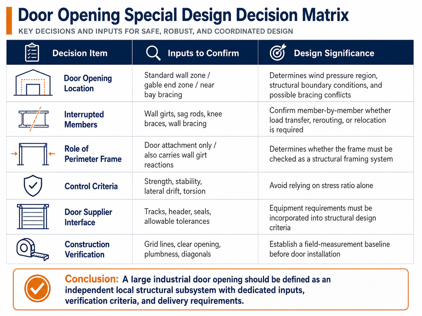
The quality of large industrial door-opening design is often revealed by details that cannot be seen in an architectural rendering: whether the end reaction of each wall girt truly has a load path; whether the jamb posts have been checked for weak-axis behaviour and torsion; whether the header satisfies both structural and equipment-related deformation requirements; whether bracing has been incorrectly interrupted to satisfy clearance needs; and whether the project ultimately produces a set of measured clear-opening data that can be handed over to the door supplier. In steel structure warehouses, the larger the opening and the closer it is to a building end or braced zone, the more these issues deserve dedicated structural treatment. In the technical coordination of such projects, Shenyang Zhongwei Heavy Industry Steel Structure Engineering Co., Ltd. should elevate the concept of “door opening dimensions” into a set of “structural interface conditions for the door opening”: every opening should be able to explain where the load comes from, through which member it passes, where it is delivered, and how sufficient operational accuracy will be maintained after the building enters service.
Item to Check |
Minimum Question to Answer |
Typical Risk |
Wall-girt termination |
Who receives the end reaction? Is the connection consistent with the calculation model? |
Underestimated jamb-post demand; local instability at the member end |
Jamb posts |
Do they simultaneously carry wall-girt reactions, door tracks, wind loads, and eccentric actions? |
Weak-axis displacement; torsion; door-track binding |
Header |
Are both upper-wall reactions and equipment deformation limits satisfied? |
Roller/track deformation; air or water leakage at the door head |
Bracing system |
Does the door opening interrupt wall bracing or sag rods? |
Discontinuity of the longitudinal lateral-load path |
Installation interface |
How will clear width, clear height, verticality, and diagonals be remeasured? |
Secondary cutting or rework after the door supplier arrives on site |
#large industrial door opening #wall girts #jamb posts #header #load rerouting #serviceability #steel structure warehouse
[1] ASCE/SEI 7-22, Minimum Design Loads and Associated Criteria for Buildings and Other Structures. Used to determine design actions, including those for wall Components and Cladding (C&C).
[2] ANSI/AISC 360-22, Specification for Structural Steel Buildings. Used for strength, stability, and connection design requirements for hot-rolled, welded, and other primary structural steel members.
[3] ANSI/SDI AISI S100-24, North American Specification for the Design of Cold-Formed Steel Structural Members. Used for the design of cold-formed C/Z wall girts and other thin-walled load-bearing members.
[4] ANSI/AISC 303-22, Code of Standard Practice for Steel Buildings and Bridges. Used to define responsibility boundaries for project documentation, fabrication/erection interfaces, and standard industry practice in structural steel projects.
[5] EN 1090-2:2018+A1:2024, Execution of steel structures and aluminium structures – Part 2. Used for fabrication and execution requirements for steel structures under the European system.
[6] ISO 4354:2009, Wind actions on structures. Provides internationally applicable basic methods for wind actions on structures.
 EN
EN