— Long Buildings Are Not About “Adding One More Joint,” but About Establishing a Controlled Deformation Path
Abstract: This article focuses on expansion and contraction issues in long steel-structure warehouses under seasonal temperature variation, solar radiation, and construction lock-in temperature. It discusses the arrangement of fixed points and release zones, the distinction between free thermal movement and additional forces caused by restraint, structural expansion joints and enclosure/MEP detailing across joints, and field acceptance of the remaining movement capacity of sliding connections. Rather than applying a simplified rule that “a joint must be provided once a certain length is exceeded,” the article follows the logic of temperature field–restraint–deformation path and proposes a project-specific design method that can be calculated, constructed, and verified.
Thermal action in steel warehouse design is often discussed only after wind, snow, and seismic actions, and is sometimes simplified to the idea that “an expansion joint should be provided once the building becomes long enough.” This approach can easily turn a structural-response problem into a purely architectural detailing problem. For warehouses, logistics centers, production buildings, and continuous multi-span portal-frame buildings with large longitudinal dimensions, the real questions are not “how many meters require one joint,” but rather: where is the structure intended to move when it heats up or cools down; which locations are allowed to release movement; which members restrain that movement; and whether the enclosure, foundations, equipment, and piping can remain compatible with the primary structure.
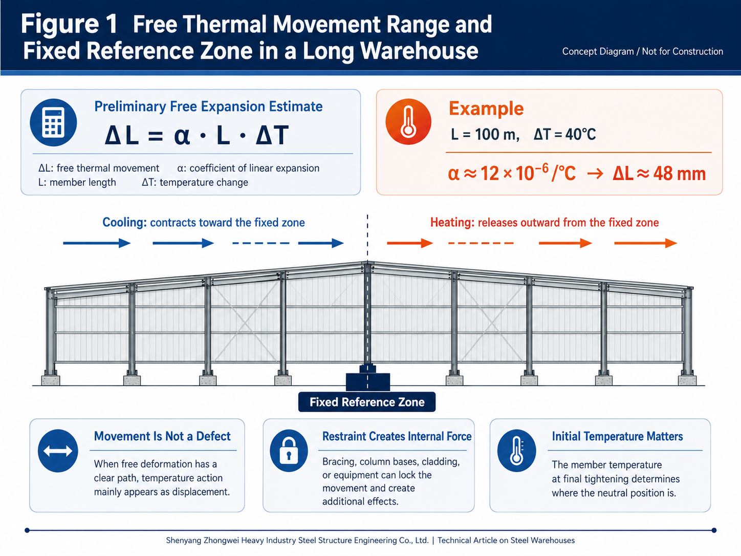
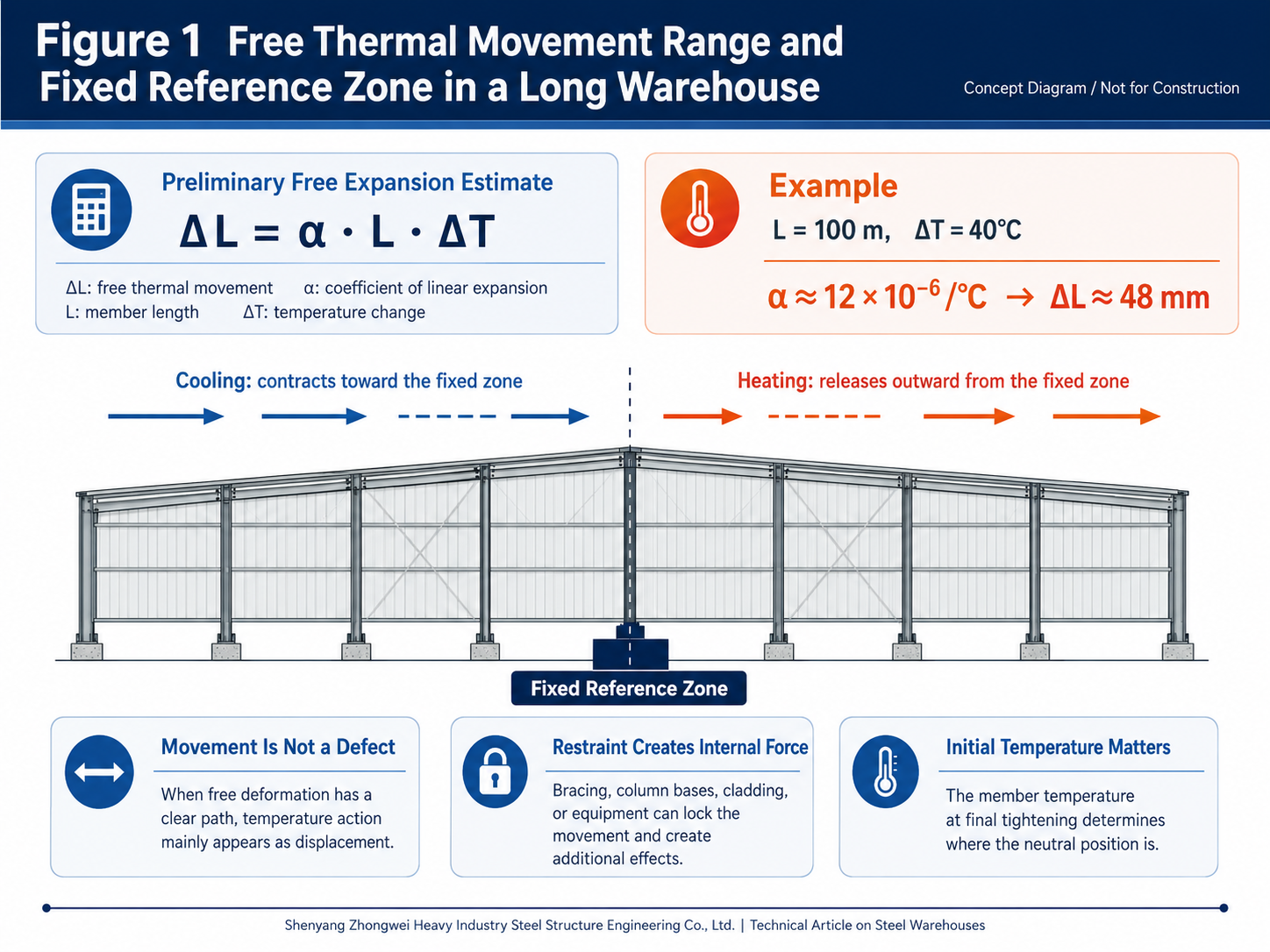
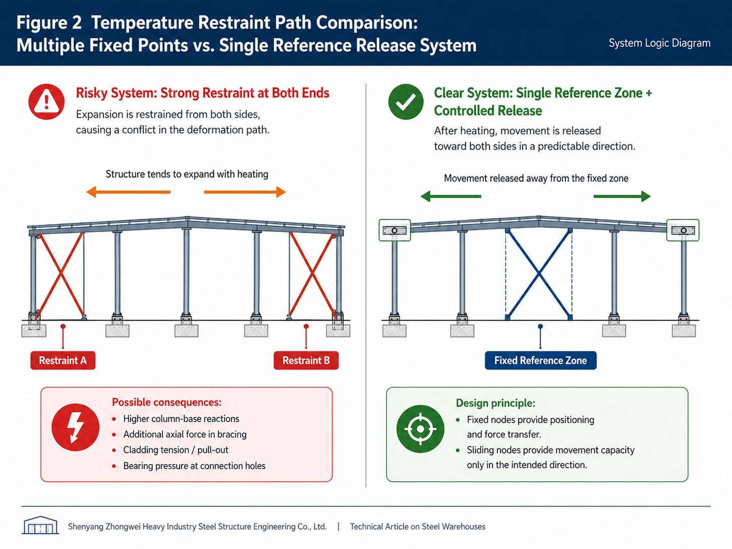
Steel expands when heated and contracts when cooled. Technical information issued by the European Commission Joint Research Centre (JRC) based on EN 1991-1-5 gives a coefficient of linear thermal expansion for structural steel of approximately 12 × 10⁻⁶/°C. Using free thermal deformation as an estimate, a 100 m-long steel structure subjected to an overall temperature change of 40°C would have a theoretical free movement of approximately 48 mm. This figure does not mean that a 48 mm-wide joint must be provided, because real buildings are affected by column-base stiffness, bracing systems, roof-sheet restraint, non-uniform member temperatures, construction initial temperature, and other factors. It does, however, clearly show that making every connection “completely immovable” does not eliminate thermal deformation; it merely converts movement into additional internal forces, local deformation, or failure of the enclosure system.
Engineers often ask: above what length must a steel warehouse be provided with an expansion joint? Once project conditions are removed from the question, there is no single answer applicable to all countries, climates, and structural systems. Building length is only one factor. The design must also consider the local temperature limits, solar radiation, whether the interior is temperature-controlled, primary structural layout, column-base configuration, location of longitudinal bracing, roof and wall materials, continuity of equipment and services, and foundation restraint. Two warehouses that are both 120 m long may experience very different thermal actions if one is an unheated building in a cold region and the other is a temperature-controlled logistics warehouse in a mild climate.
EN 1991-1-5 treats thermal actions as an independent category of structural action and distinguishes between the uniform temperature component, temperature gradients, and temperature differences between different structural members. For warehouse-type buildings, the most common effects are the uniform temperature rise or fall affecting the structure as a whole and temperature differences between the roof, external walls, and internal members caused by solar radiation. For dark-colored metal roofing, member temperature is also influenced by solar radiation and surface absorptivity; therefore, the “local maximum air temperature” cannot be mechanically equated to the “maximum steel-member temperature.”
Long warehouses usually contain several longitudinal stability bays or zones. The key design principle is to avoid multiple strong restraints working against one another. If the longitudinal bracing system forms strong fixed restraints at both ends of the building while intermediate members remain continuously connected, the structure wants to elongate during heating but has no clearly defined release direction. Thermal forces then accumulate in columns, bracing, column bases, and connections. A clearer approach is to establish the concept of a “fixed zone–release zone”: the fixed zone provides the longitudinal reference position and transfers horizontal forces, while the release zone allows temperature-induced movement to be progressively accommodated. “Release” does not mean a loose connection. It means creating a predictable movement path through bracing arrangement, sliding details, slotted holes, deformable connections, or segmented structural systems.
Free thermal movement can be preliminarily estimated using ΔL = αLΔT. This equation is useful for understanding the order of magnitude of movement, but it should not replace structural analysis. The actual thermal response of a steel structure depends on restraint stiffness: where a member can expand freely, the response is mainly displacement; where it is strongly restrained, thermal strain is converted into axial force; and real buildings usually lie somewhere between these two conditions. ASCE/SEI 7-22 includes temperature effects, shrinkage, and similar effects within the design framework for self-straining forces and effects, and its serviceability provisions require dimensional changes caused by temperature variation and similar effects not to impair structural function.
Thermal-action design should therefore consider at least three levels simultaneously. First, the primary structure: longitudinal column lines, longitudinal bracing, tie members, roof horizontal bracing, and column bases together determine the global restraint condition, and the supports and releases in the analytical model must match the actual detailing. Second, the connections: if the design intent is to permit movement, the sliding direction, hole geometry, plate or washer dimensions, bolt behavior, and installation starting position must be clearly defined; movement cannot be achieved by an informal instruction such as “do not tighten the bolts too much.” Third, non-structural components: wall panels, roof panels, doors and windows, gutters, rooflights, and pipe supports must all be coordinated with primary-structure movement. Passing the structural calculation does not mean that the enclosure details are automatically safe.
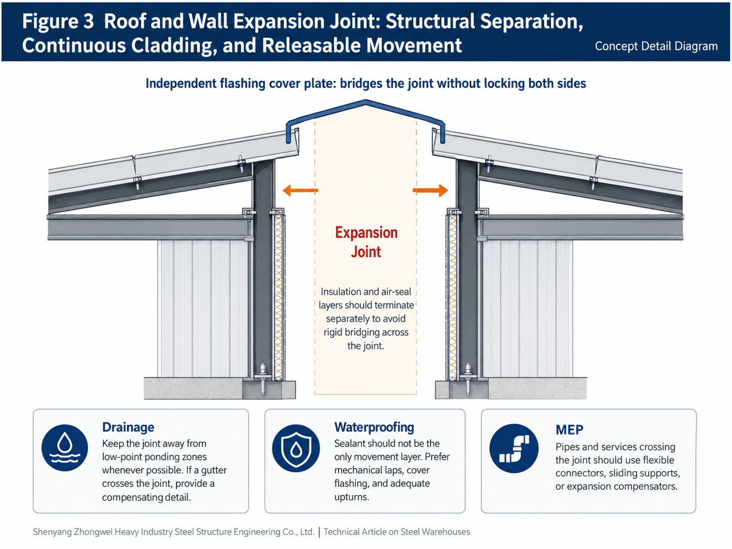
For multi-span portal-frame warehouses, where a structural expansion joint is provided, the structures on both sides of the joint should generally form relatively independent structural units. It is not sufficient merely to cut the roof sheeting while keeping the main steel frames rigidly continuous. Conversely, even where structural analysis shows that the primary structure can be built without a structural expansion joint, thermal expansion and contraction of the enclosure system must still be considered. Roof sheets, wall sheets, eave flashings, gutters, and rooflights are usually thinner and more sensitive than the main steel frame. A primary structure that “passes the calculation” does not mean the enclosure will not first suffer cracking, buckling, oil-canning, or repeated bearing at fastener holes.
A mature expansion-joint detail must address structural behavior, waterproofing, thermal insulation, fire protection, and building-use requirements at the same time. Roof expansion joints should, where possible, be located away from low points where water can pond. Where this cannot be avoided, the waterproofing system should be designed to remain continuous while accommodating movement, rather than relying on a single bead of sealant to absorb the entire displacement. Metal roofs can accommodate movement through independent flashing caps, adequate upstands, sliding laps, and separate fixing on both sides. Wall details must similarly provide weather sealing and visual continuity: wall sheets on each side of the joint should be independently terminated, and the cover flashing between them must retain sufficient lap travel.
Gutters, parapets, rooflights, and MEP systems that cross the joint must also be checked carefully. If the structural engineer separates the primary structure at a grid line but a continuous gutter, self-drilling screws, a fire main, or a cable tray rigidly reconnects the two sides, the site installation has effectively recreated a hidden fixed point.
Table 1. Common “Object – Incorrect Assumption – Correct Control Parameter” Issues in Thermal-Action Design
Object |
Common Incorrect Assumption |
Specialized Control Focus |
Primary structure |
Determine whether a joint is required only from the total building length |
Temperature range, restraint stiffness, bracing location, column bases, and release direction |
Sliding connection |
The longer the slotted hole, the safer the connection |
Design movement direction, hole geometry, washer/plate coverage, force-transfer mechanism, and initial position |
Enclosure system |
If the primary structure has no joint, the enclosure needs no movement release |
Panel length, fixing method, flashing laps, and independent movement of gutters and edge trims |
MEP / equipment |
Structural joints are unrelated to services |
Travel of expansion compensators/flexible couplings, sliding supports, and continuity of equipment rails |
Construction acceptance |
A neat-looking connection is acceptable |
Lock-in temperature, remaining slotted-hole travel, fixed-point location, and hidden restraints across joints |
One of the most common site optimization measures is to replace standard circular holes with slotted holes when longitudinal movement is found to be restricted. This approach is valid only when the connection force-transfer logic, sliding direction, and bearing conditions are clearly defined. First, the long axis of the slot must align with the intended movement direction. Second, whether the connection is permitted to slip under wind load, braking force, or other horizontal actions must be consistent with the global structural system. If the connection transfers critical horizontal force, simply enlarging the hole may alter the intended load path. Third, cover plates or washers must effectively cover the slot and prevent local pull-through after installation.
For high-strength bolted connections, a distinction must also be made between slip-critical connections, bearing-type connections, and sliding connections specifically intended to release movement. If the design documents require a connection not to slip under service loads while simultaneously expecting it to release thermal displacement by movement within the hole, the two operating conditions and their respective mechanisms must be explicitly defined. The essence of professional design is not the use of any particular connection type, but that each connection performs only the function assigned to it: fixed connections provide positioning and force transfer, while sliding connections provide movement capacity in a specified direction.
An expansion joint may be provided in the steel superstructure, but whether foundations and floor slabs should be jointed at the same location must be determined according to the structural system and building function. If the foundations on both sides are effectively tied into a very stiff continuous system while the superstructure is intended to move relatively, unnecessary restraint may develop at the column bases. Conversely, if the foundations are independent but the superstructure is rigidly reconnected by continuous members, the effectiveness of the joint is similarly reduced.
Industrial warehouses require particular attention to equipment systems. Fire mains, cable trays, compressed-air lines, steam pipes, conveyor lines, and storage-racking systems may all cross a structural joint. If the structural design movement is not communicated to the MEP and equipment disciplines, rigid piping may crack, supports may deform, or equipment rails may become misaligned during service. Services crossing a joint should use flexible couplings, sliding supports, expansion compensators, or independent supports. Their movement capacity should cover the required structural design displacement while also allowing for installation tolerances.
Thermal action includes another variable that is often overlooked: the temperature at which the structure is finally locked in. The initial temperature assumed in analysis is not necessarily equal to the annual mean air temperature. It is related to the actual temperature when members are erected, connections are finally tightened, and the roof system is closed. The design may assume that the structure is in a neutral position near a moderate temperature, but if all fixed connections are finally locked after prolonged solar heating during midsummer, the subsequent contraction movement during cooling may become strongly biased toward one side.
For sliding connections with large movement demand, long roof sheets, continuous gutters, and large door openings, construction documents should consider specifying whether lock-in temperature, initial connection position, and reserved movement allowance are to be recorded. A truly executable connection drawing should state the sliding direction, design movement, installation mid-position, permitted tolerance, and final fixing requirements, so that installers know whether the component should be centered within the slot, biased toward one end, or adjusted according to the measured installation temperature.
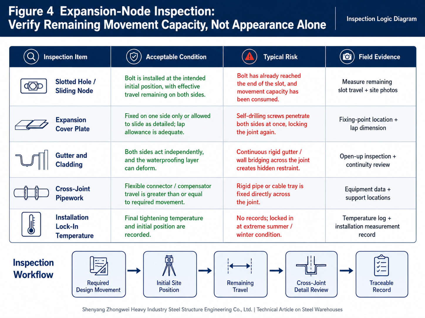
Acceptance of movement-release details should not be limited to checking whether bolts are aligned or cover plates are straight. More importantly, the inspection must confirm that the movement capacity required by design remains available after construction. Common site failures include: a bolt already bearing against one end of a slotted hole; a sliding surface locked by tack welds; cover-plate screws penetrating substrates on both sides of the joint; sealant completely filling and locking the gap; a continuous gutter reconnecting two structural units; MEP supports rigidly spanning the joint; and wall-panel flashings installed without sufficient sliding lap. These details may appear very neat while having already lost their intended movement function.
Acceptance records should therefore include, at a minimum, the actual expansion-joint width, initial position of sliding connections, remaining travel in slotted holes, enclosure detailing across the joint, pipework compensation method, and site lock-in temperature. For warehouses in long-term service, simple measurement reference points can also be established on both sides of the joint so that seasonal movement and abnormal deformation can be rechecked.
Thermal deformation is a fundamental physical response of the material. What design can actually control is the restraint condition, load-transfer path, and permitted movement. For steel warehouses, the most hazardous situation is often not the displacement itself, but rather that “a location that should move has been locked, while a location that should remain fixed has slipped.”
A professional thermal-action design should establish a clear logic: first define the project temperature limits and expected member-temperature range, then estimate the order of magnitude of free thermal deformation; next identify fixed points and sources of restraint in the primary structure and establish a clear release direction; then determine whether structural expansion joints are required and how the enclosure, foundations, and equipment systems will cross them; finally, translate design displacement into connection parameters that can be understood during construction and measured during acceptance. For overseas warehouse and industrial-building projects served by Shenyang Zhongwei Heavy Industry Steel Structure Engineering Co., Ltd., climate, construction temperature, enclosure systems, and equipment conditions vary significantly from country to country. Thermal action should therefore not be reduced to a fixed building-length table; it should be treated as a project-specific design input requiring engineering judgment. A truly reliable solution does not attempt to make the structure completely “immovable”; it ensures that every millimeter of movement has a clearly defined destination.
#steel-structure warehouse #thermal action #expansion joint #thermal expansion and contraction #sliding connection #slotted hole #construction lock-in temperature
1. EN 1991-1-5:2003, Eurocode 1: Actions on structures – Part 1-5: General actions – Thermal actions. Used for classification of thermal actions, temperature components, and the analytical framework for structural thermal effects; specific projects should be coordinated with the applicable National Annex and locally adopted edition.
2. ASCE/SEI 7-22, Minimum Design Loads and Associated Criteria for Buildings and Other Structures. Its basic requirements and load combinations include self-straining forces and effects; Appendix C serviceability provisions require dimensional changes caused by temperature and similar effects not to impair structural function.
3. ANSI/AISC 360-22, Specification for Structural Steel Buildings. Used for structural-steel member, connection, and serviceability design in conjunction with the action framework of ASCE 7; AISC’s current standards page identifies 360-22 as the current edition.
4. ANSI/AISC 303-22, Code of Standard Practice for Steel Buildings and Bridges. Used for engineering practice requirements related to structural design documents, fabrication and erection, tolerances, and professional coordination.
5. AISC Design Guide 3, Serviceability Design Considerations for Steel Buildings, 2nd Edition, 2003. The serviceability topics covered include expansion and contraction and may be used as supplementary technical guidance for thermal deformation and movement-release detailing; its publication date should be considered and the guidance coordinated with current standards.
6. European Commission JRC, Handbook 3: Action Effects for Buildings, Chapter IV “Thermal Actions on Buildings.” This chapter, based on EN 1991-1-5, explains temperature fields, uniform temperature components, and restraint effects, and gives an engineering reference value of approximately 12 × 10⁻⁶/°C for the coefficient of linear thermal expansion of structural steel.
 EN
EN