Topic Scope |
Article Category |
Core Criterion |
Introduction
In steel warehouse fabrication, welded H-section columns, crane girders, and tapered portal-frame rafters are established products. In batch production, however, the real challenge is whether the member retains the drawing-required straightness, section squareness, hole relationships, and erection interfaces after welding. Many shops weld first and correct excess distortion later with a straightening machine or flame heating. This may improve the visible shape while leaving high residual stress, repeated thermal cycles, and dimensional drift. |
In steel warehouse fabrication, welded H-section columns, crane girders, and tapered portal-frame rafters form continuous interfaces with end plates, high-strength bolt-hole groups, purlin cleats, base plates, crane-girder corbels, and secondary cladding members. A few millimetres of sweep may be inconspicuous during single-member inspection, yet after accumulation across multiple bays it can appear as column-grid offset, an uneven ridge line, or misaligned purlin holes. In warehouses equipped with cranes, crane-girder camber, twist, and end-elevation errors can also reduce the available range for rail alignment.
Accordingly, the objective of distortion control is not to make every member “absolutely straight,” but to establish clear boundaries among fabrication tolerance, specified camber, and erection adjustment capacity. ISO 13920:2023 provides a general tolerance framework for linear dimensions, angles, shape, and position in welded constructions, and stresses that the tolerance class should be selected according to the member’s function; dimensions individually specified on the drawings take precedence.[2] ANSI/AISC 303-22, from the perspective of standard practice for steel buildings and bridges, defines generally acceptable accuracy limits for contracting, fabrication, and erection.[6] These documents serve different purposes: one helps define welding-fabrication tolerances, while the other helps the parties establish contractual and erection-interface expectations. They are not interchangeable.
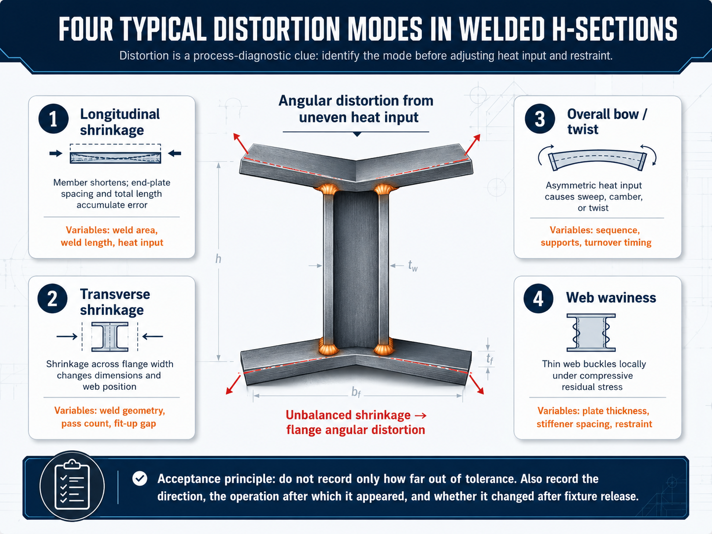
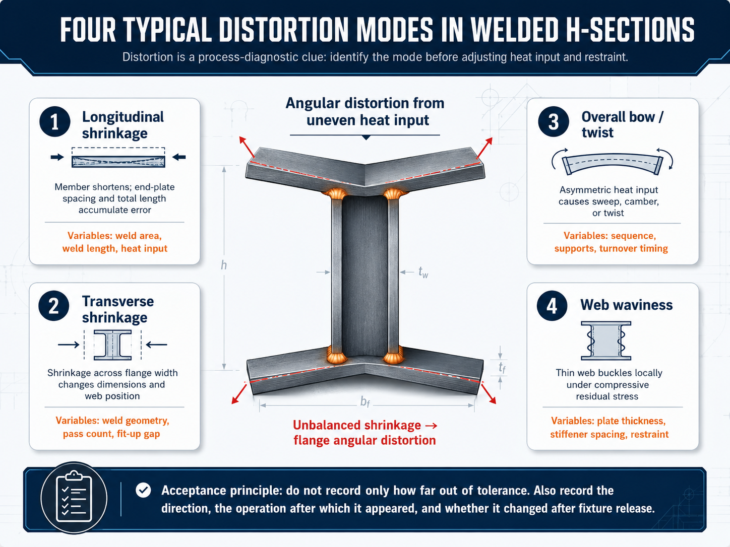
Typical distortion modes in welded H-sections include longitudinal shrinkage, transverse shrinkage, flange angular distortion, overall sweep or twist, and local waviness in thin webs. Longitudinal shrinkage causes cumulative changes in member length, end-plate spacing, and hole-group datums; transverse shrinkage mainly affects flange-width dimensions and web position; angular distortion results from the through-thickness temperature gradient at the weld; overall bending or twist usually indicates asymmetry in heat input, welding timing, or support conditions on the two sides of the member.
Even the same symptom—“sweep”—can have very different causes. If the member deflects immediately after the long weld on the first side is completed and partially springs back after turning and welding the opposite side, the primary cause is usually an unbalanced welding sequence. If dimensions are acceptable at the end of welding but significant bending appears only after heavy clamps are released, the restraint temporarily locked in shrinkage and residual stresses redistributed after release. If web waviness occurs only between stiffeners, check the web thickness, stiffener welding sequence, and local excessive heat input rather than simply increasing reverse camber for the whole member.
Fabrication records should preserve not only the numerical deviation but also its direction, the operation after which it appeared, measurement temperature, and fixture status. Only with this information can the next batch be improved by adjusting the welding sequence or preset, rather than repeatedly relying on manual straightening.
Distortion control starts with fit-up, not with striking the arc. The web centerline, flange edges, end-plate datum faces, and hole-group centers must be related to one common fabrication datum system. If the assembly jig is not level, support heights are inconsistent, or support locations change after the member is turned, measured sweep and twist will include support error. For long members, define three datum systems: end datums for length and hole locations; the web centerline and flange edges for section squareness; and specified supports plus a chord line or laser datum for overall straightness.
During fit-up, also confirm web-to-flange contact, root gaps, tack-weld locations, and the stiffener installation sequence. Large variations in gap along the length change the actual deposited weld-metal volume and ultimately create uneven shrinkage. Tack welds are not merely temporary “holding” points; their length, spacing, and quality must maintain assembly accuracy and must not leave cracks, lack of fusion, or abnormal surfaces to be covered by the production weld. AWS D1.1/D1.1M:2025-AMD1 covers the basic requirements for structural-steel welding fabrication, procedure qualification, and inspection, and can serve as a key basis for the project welding-control documentation.[1]
For repetitive production members, a small reverse-camber preset or length allowance may be established from first-article data, but the value must be derived from measured trends for the same section, weld configuration, and tooling. Directly applying an empirical value from one project to different plate thicknesses, groove details, or welding equipment often leads to overcorrection. The purpose of presetting is to offset predictable shrinkage, not to intentionally create a different out-of-tolerance condition in advance.
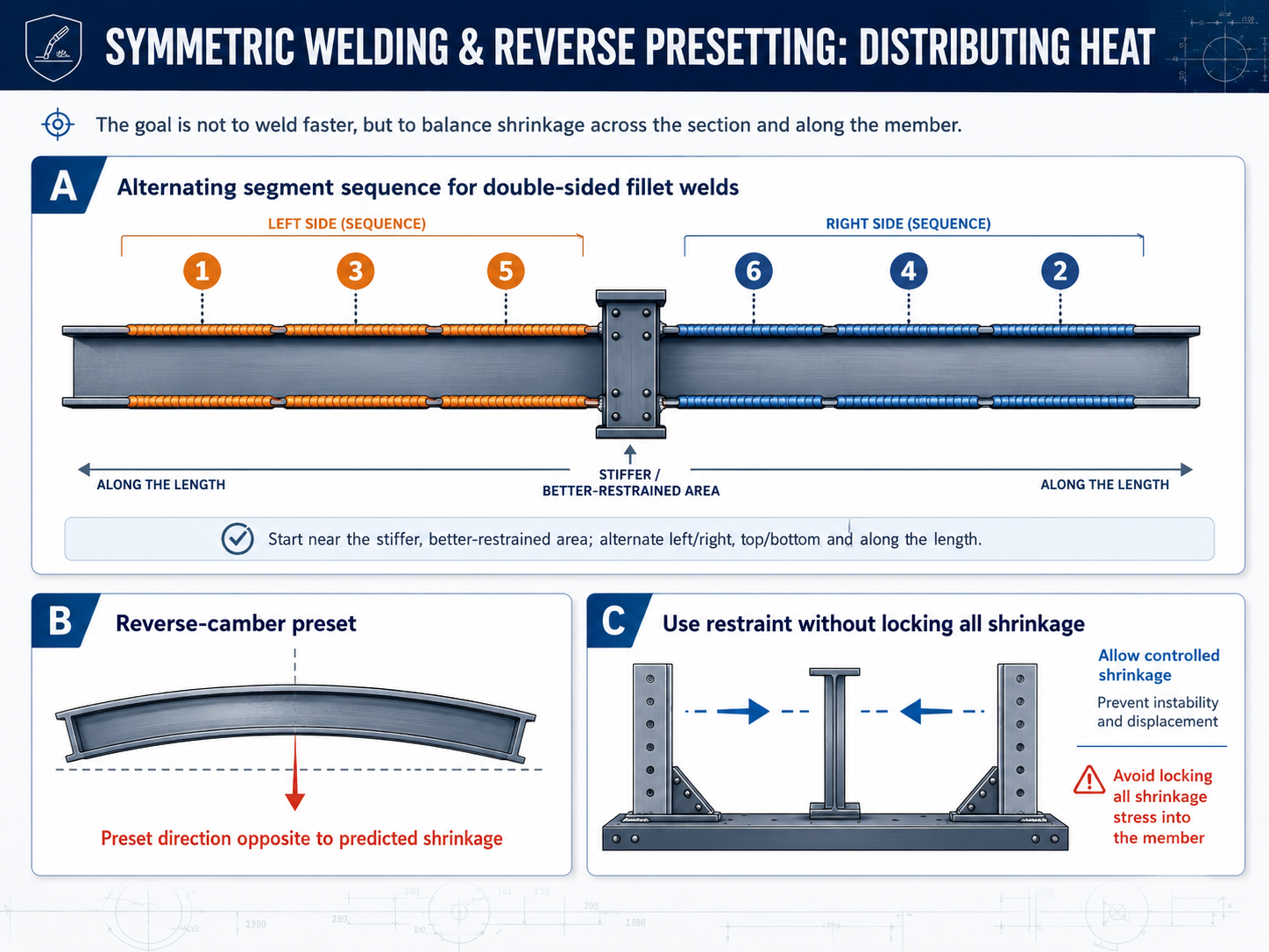
The distribution of heat input on both sides of the section and along the member length determines whether shrinkage can balance itself. For double-sided fillet welds between web and flange, common approaches include left-right symmetry, top-bottom alternation, skip welding in segments, or progression from stiffer regions toward free ends. The specific sequence must be written into the welding procedure or work instruction and matched to welding position, equipment quantity, and turnover method; it is not enough to write “symmetrical welding” only in the inspection plan.
For long welds, continuous welding from one end to the other is easy to organize, but it causes longitudinal heat and shrinkage to accumulate progressively. Back-step or skip welding can change the accumulation path, yet segment length, overlap, and arc-start/arc-stop treatment must still ensure weld quality; distortion reduction must not create lack of fusion, craters, or discontinuities. ISO 5817:2023 defines quality levels B, C, and D for imperfections in fusion-welded joints, with B being the most stringent; it assesses weld imperfections, not member geometric tolerances.[3] This distinction is essential: a weld can meet its imperfection quality level while the member remains geometrically out of tolerance; conversely, a member straightened to acceptable shape does not automatically have acceptable internal weld quality.
Heat-input control likewise requires consistency, not simply the lowest possible value. Excessive heat input enlarges the heated zone and increases shrinkage, while insufficient heat input can cause incomplete fusion or frequent arc interruptions. Production control should remain within the approved WPS and manage current, voltage, travel speed, interpass temperature, and bead size. Equipment parameter logs or shop-floor inspections should be used to identify unbalanced heat input between the two sides.
Jigs, press beams, and lateral stops can prevent instability or obvious movement during welding, but fully locking shrinkage does not eliminate distortion. Heavy restraint increases restraint stress in the weld and base metal, and springback may still occur after fixtures are released. With thick plate, high-strength steel, or highly restrained joints, cold cracking and lamellar tearing also require attention. Appropriate restraint should allow controlled longitudinal shrinkage while preventing section rollover, web instability, and irrecoverable displacement during welding.
Reverse presetting is suitable for members with a stable distortion direction and a clear batch pattern. For example, if H-beams of the same section consistently bend toward the side welded first, a small reverse pre-bend can be applied during assembly so that the member approaches the target line after both sides are welded. The preset should be refined gradually using the first article and the next few members, and an upper limit should be established. If distortion direction varies randomly within the same batch, the problem is more likely inconsistent support points, fit-up gaps, welder operation, or turnover timing; increasing the preset will only increase the variation.
For tapered portal-frame rafters, do not assess only the member centerline. Changing section depth alters stiffness and heat dissipation along the length; the same welding parameters may create more pronounced angular distortion at the shallow end and greater longitudinal shrinkage restraint at the deep end. A more effective method is to define the welding sequence and support arrangement by section zone rather than applying one fixed rhythm along the entire member.
Straightening should be considered only when the member remains outside the drawing or applicable tolerance after cooling and release of temporary fixtures. Mechanical straightening uses a press, flange-straightening machine, or dedicated fixture to apply controlled reverse deformation. Because it introduces less thermal effect and is easier to repeat, it should normally be the preferred option. Load and support points must be controlled to avoid creating new local buckling or surface indentation at hole groups, cutouts, weld toes, or abrupt section changes.
Flame straightening changes member geometry through local heating and subsequent cooling shrinkage; common patterns include line, triangular, and spot heating. It is not an improvised practice of “heating the steel red and quenching it,” but a controlled process requiring material identification, heating-zone design, temperature monitoring, and measurement feedback. Temperature limits, permitted cooling methods, and repeated-heating limits must be determined from the steel grade, supply condition, design requirements, and applicable standards. Experience from ordinary carbon steel must not be applied indiscriminately to quenched-and-tempered steel, thermomechanically rolled steel, or other property-sensitive materials. Visual estimation by color must not replace temperature measurement, and rapid cooling should not be used without approval.
AWS D1.1 includes requirements for straightening and heat treatment in structural-steel fabrication,[1] while ISO 3834-2:2021 requires manufacturers to maintain comprehensive quality control over welding personnel, procedure documents, equipment, inspection, and nonconformance disposition.[4] At a minimum, an internal flame-straightening procedure should define the heating pattern, travel direction, temperature-measurement locations, heating equipment, cooling method, allowable correction per cycle, and stop criteria. If cracks, lamellar tearing, abnormal hardening indications, or weld-toe damage appear in the straightened area, work must stop immediately and be referred for engineering review.
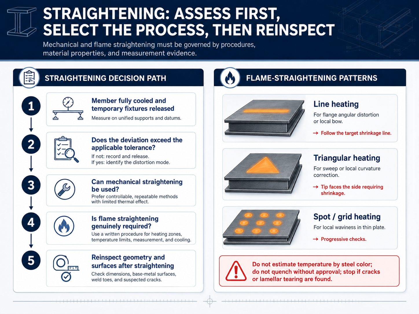
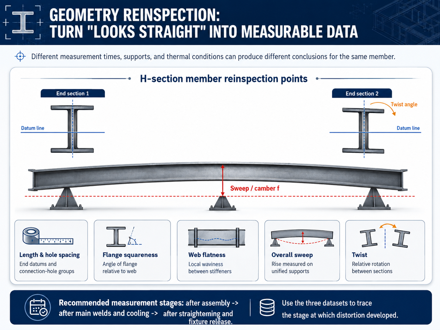
Hot members can exhibit temporary distortion due to temperature gradients, while forced clamping can conceal true springback. Final geometric inspection must therefore be performed after the member has fully cooled, temporary restraints have been released, and the member has been placed on the specified supports. Support locations and quantity for long members must be fixed; otherwise, self-weight deflection may be misidentified as weld-induced sweep. For members in the same batch, inspectors should use the same arrangement of chord lines, lasers, feeler gauges, straightedges, or total stations, and record ambient temperature and member condition.
Three measurement stages are recommended: record the initial line after assembly; record the as-welded distortion after the main welds are completed and the member has cooled; and record the final dimensions after straightening and fixture release. These three datasets show whether the deviation originated during assembly, welding, or straightening. If only the final conforming values are retained, production personnel cannot determine which side’s heat input should be reduced in the next batch or identify whether a straightening machine is systematically overloading members.
Final inspection should cover, at minimum, overall length, end datums, relative hole-group location, section depth and width, flange-to-web squareness, local web flatness, overall sweep or camber, twist, and mating surfaces of connection plates. Weld surface inspection may be performed in accordance with ISO 17637:2016, which specifies methods for visual testing of fusion-welded joints and may also be applied to pre-weld joint inspection.[5] Geometric dimensions and weld quality should be recorded and accepted separately; the vague statement “appearance acceptable” should not be used as a substitute.
The key to controlling distortion in welded H-sections is not the tonnage of the straightening equipment available at the end of the line, but the ability to predict shrinkage direction and establish a stable combination of heat input, welding sequence, supports, and presetting. The distortion mode is a “result fingerprint” left by the process: consistent direction calls for correction of system parameters; random direction calls for investigation of fit-up and execution variability; deviations appearing only after fixture release indicate that the restraint method needs adjustment.
Professional fabrication control should achieve three things: unified datums and a first-article target before welding; executable heat-input and sequence rules during welding; and cold, unrestrained, uniformly supported geometric evidence after welding. Mechanical or flame straightening can only be controlled corrective tools; they cannot replace front-end process design. With this approach, welded H-sections can arrive at the warehouse site not only with acceptable welds, but also with stable dimensions for erection.
No. |
Standard / Specification |
Purpose in This Article |
1 |
AWS D1.1/D1.1M:2025-AMD1 — Structural Welding Code—Steel. |
General technical basis for structural-steel welding fabrication, procedure qualification, straightening, and inspection. |
2 |
ISO 13920:2023 — General tolerances for welded constructions. |
General tolerance framework for linear dimensions, angles, shape, and position in welded constructions. |
3 |
ISO 5817:2023 — Quality levels for imperfections in fusion-welded joints. |
Used to distinguish weld imperfection quality levels B, C, and D; does not replace member geometric tolerances. |
4 |
ISO 3834-2:2021 — Comprehensive quality requirements for fusion welding. |
Comprehensive quality management for welding personnel, procedures, equipment, inspection, and nonconformance disposition. |
5 |
ISO 17637:2016 — Visual testing of fusion-welded joints. |
Visual testing methods for pre-weld joints and completed fusion welds. |
6 |
ANSI/AISC 303-22 — Code of Standard Practice for Steel Buildings and Bridges. |
Standard practice and normal accuracy limits for steel fabrication, delivery, and erection coordination. |
 EN
EN