Topic Scope |
Article Type |
Applicable Projects |
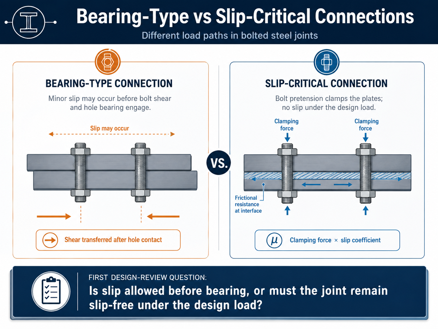
In steel-structure warehouse projects, high-strength bolted connections are often reduced to a simple check: “the bolt grade is compliant and the required torque has been reached.” That judgment is already inadequate for ordinary bearing-type connections and can be fundamentally wrong for slip-critical connections. A slip-critical joint does not rely on the bolt shank first bearing against the hole wall. Instead, bolt pretension clamps the connected plates so that shear is resisted at the faying surfaces. In other words, the working system is not an isolated bolt; it is the complete combination of bolt, nut, washer, faying surface, ply fit, tightening tool, and installation procedure. |
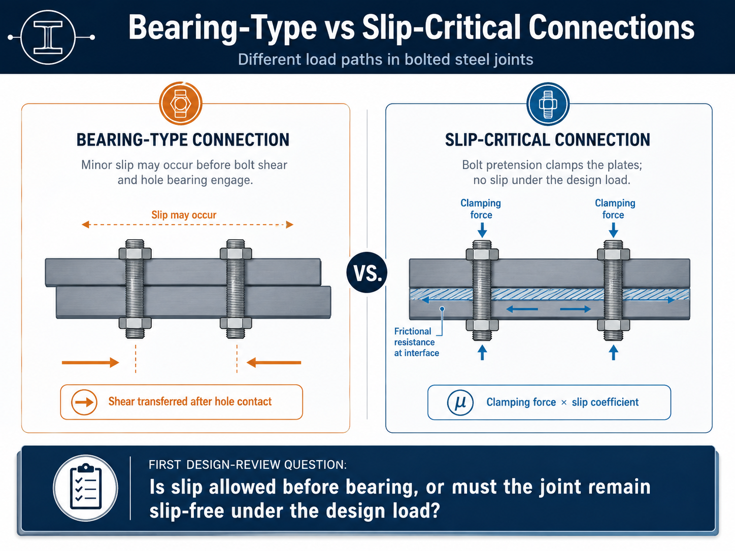
Bearing-type and slip-critical connections may both use high-strength bolts, but their load paths are different. Under shear, a bearing-type connection may first experience clearance take-up and minor slip; load is then carried jointly by bolt shear, bearing at the hole wall, and the member net section. A slip-critical connection, by contrast, requires that the faying surfaces undergo no relative movement that would impair serviceability or safety under the specified design condition. RCSC 2020 describes a slip-critical joint as one in which friction, developed by the clamping force of pretensioned bolt assemblies, resists the design load and prevents movement at the faying surfaces.[1]
Accordingly, a drawing note that says only “Use Grade 10.9 high-strength bolts” still omits essential design information. At a minimum, the connection category, faying-surface treatment, design slip coefficient, bolt-pretensioning method, and inspection level should be specified. For warehouse joints supporting cranes, conveyors, vibrating platforms, slotted holes, or deformation-sensitive components, whether slip is permitted directly affects rail elevation, bracing stiffness, and cladding interfaces. In a specialist design review, the first task is not to check torque; it is to confirm that the design documents clearly state the performance objective of “no slip.”
Many projects treat the slip coefficient as an inherent property of the steel grade, or even assume that a blasted surface is better simply because it is “rougher.” In reality, slip resistance depends on the faying-surface class, roughness profile, level of contamination, coating system, cure condition, assembly pressure, long-term relaxation, and other factors. The same steel can perform very differently after different shot-blasting processes, primers, or storage environments.
RCSC sets separate requirements for uncoated, blast-cleaned, hot-dip-galvanized, and qualified coated faying surfaces, and requires the coating system to be tested before it is used in a slip-critical joint. It also warns that overspray from an unqualified coating within the bolt-group area can substantially reduce slip resistance.[1] EN 1090-2:2018+A1:2024 addresses the preparation, assembly, and tightening of connection surfaces from the perspective of steelwork execution.[2] For the fabrication shop, faying-surface control cannot stop at a process-card note such as “blast to Sa 2.5.” The documents must also define areas that shall remain unpainted, permitted temporary protection, the maximum time before assembly, and the required response to flash rust, oil contamination, or rain exposure.
One of the most common site misjudgments is to regard a light, uniform film of flash rust as a natural anti-slip layer. Whether such rust is acceptable must follow the surface class and project standard specified by design; it cannot be decided by color alone. Another recurring problem is inadequate masking during overall coating, allowing finish paint or zinc-rich primer mist to enter the edge of the faying surface. Although the contamination may appear discontinuous, it can create a weak interface. The correct approach is to define the faying surface as a separate quality-control zone, use masking templates resistant to blasting and spraying, and link member numbers, connection-plate numbers, and inspection records.
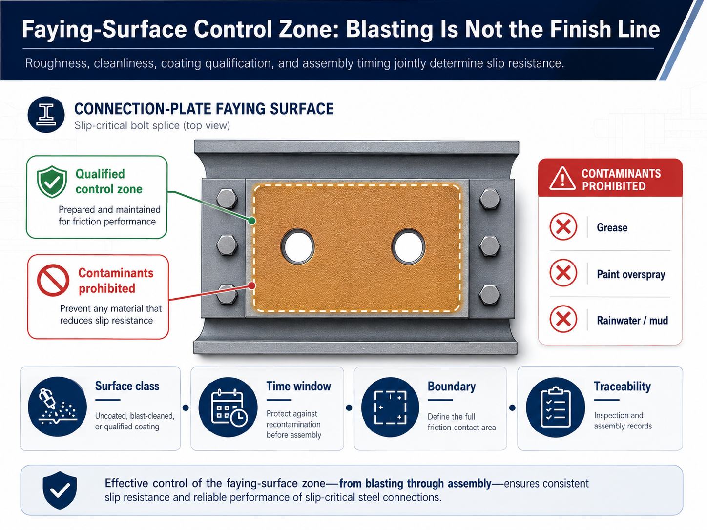
Once a faying surface has been shot-blasted or sandblasted, its quality is not permanently locked in. During handling, marking, hole reinspection, outdoor storage, and waiting for erection, the surface may still be contaminated by perspiration, cutting fluid, diesel exhaust, mud, water, or rust-preventive oil. In coastal, high-humidity, or winter-condensation environments, the condition of a treated plate may change within only a few hours.
The production plan should place faying-surface treatment close to trial assembly or shipment instead of completing it weeks in advance merely to maximize blasting-line efficiency. Connection plates and main members should be stored in separate zones, and oily separator paper must not be placed directly between faying surfaces. Lifting should use lifting lugs or soft slings that do not contact the controlled area. For projects using coated faying surfaces, records should identify the coating manufacturer, product name, batch number, dry-film thickness, application environment, and curing time; a primer of the “same color” is not a substitute for qualification evidence.
Geometric quality of the faying surface is equally important. Burrs around holes, flame-cutting slag, local distortion, or weld spatter can create point contact between plies. Bolt pretension is then consumed in flattening defects rather than converted uniformly into clamping force. Before assembly, verify surface flatness, ply fit, and hole concentricity. Never use final tightening to pull obviously misaligned plates into position; doing so makes some bolts act first as alignment devices and then causes pretension to redistribute as adjacent bolts are tightened.
Torque is only an input to the tightening process; pretension is the result required by a slip-critical connection. Most input torque is consumed by thread friction and friction under the nut bearing surface. The proportion converted into axial bolt elongation changes with lubrication, coating, thread tolerance, corrosion, washer hardness, and tool condition. ISO 16047 specifies test conditions for the torque/clamp-force relationship of threaded fasteners precisely because that relationship must be measured under controlled conditions.[3]
RCSC commentary explains that, unless the relationship is established for the specific bolt lot, diameter, and assembly condition, the scatter between torque and pretension may be very large. The specification therefore does not accept pretension inferred directly from a generic table or simple formula.[1] This is the root cause of some cases in which “every torque reading passed, yet the connection still slipped”: the record captured wrench output rather than the actual condition of the clamping system.
The calibrated-wrench method is not inherently wrong, but its calibration must apply to the same day, lot, diameter, assembly condition, and tool. Dust contamination after bolts are removed from sealed packaging, changes in battery charge or air pressure, and socket wear can all invalidate the original calibration. Lubricant must not be added to high-strength bolts in the field unless expressly allowed by the bolting system and project procedure. Too little lubrication can cause seizure or torsional fracture; excessive lubrication can generate excessive pretension at the same torque.
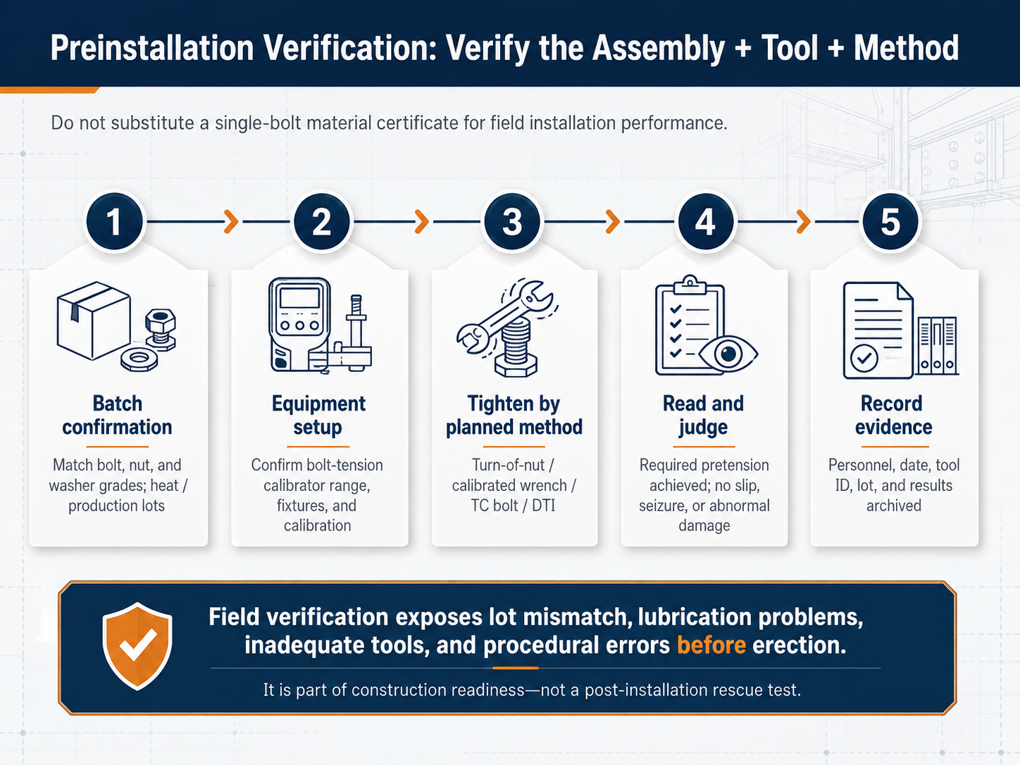
Preinstallation verification should be carried out at the installation site using the complete bolt assemblies and tightening tools intended for the work. The object is not the tensile strength of one bolt; it is whether the combination of “bolt + nut + washer + surface condition + tool + tightening method” can consistently achieve the specified pretension. RCSC requires preinstallation verification for the selected installation method and the use of a bolt-tension measuring device to confirm assembly performance while identifying inadequate lubrication, over-tapped nuts, mismatched components, and insufficient tool capacity.[1]
In execution, first confirm that the bolts, nuts, and washers are approved matching grades and sizes, and that packaging and lot identification have not been mixed. Next check the range of the tension-measuring device, fixture dimensions, and calibration status. The actual erection crew should then complete tightening using the planned turn-of-nut method, calibrated-wrench method, twist-off-type tension-control bolts, direct tension indicators, or an approved combination. The record should include, at minimum, the date, connection size, lot, sample quantity, tool identification, operator, target value, measured results, and any abnormal condition.
Preinstallation verification has another frequently overlooked value: before members are erected, it gives installers and inspectors a common understanding of the “snug-tight condition,” “match marks,” “required rotation,” “DTI gap,” or “spline-off condition.” If the parties wait until work is at elevation to debate whether tightening is acceptable, rework cost and safety risk multiply. Verification should be repeated in accordance with the project procedure when work continues over multiple days, tools are changed, lots change, or storage conditions change materially; one test must not be treated as a permanent pass for the entire project.
The turn-of-nut method controls tightening through bolt elongation. After the joint is brought to the correct snug-tight condition, the specified rotation is applied. RCSC considers the method generally capable of producing more reliable pretension than a method that depends entirely on torque, but it requires the plies to be fully brought into contact, the turned element to be clearly identified, and tightening to proceed systematically from the stiffest part of the connection outward.[1] For joints whose bolt length, slope condition, or washer arrangement falls outside normal tabulated limits, the required rotation should be confirmed with an appropriate tension-measuring device.
The calibrated-wrench method suits projects with stable work organization and strict tool management. Calibration frequency, the turned element, and tool output must remain within the verified conditions. Twist-off-type tension-control bolts provide a visible construction signal when the spline shears off and are efficient for large-volume installation, but spline-off does not automatically prove that the faying surface is compliant, nor does it replace snug tightening and assembly-lot control. Direct tension indicators provide visible pretension evidence through protrusion compression and feeler-gauge inspection, but washer orientation, gauge thickness, contact-surface condition, and inspection location must be consistent.
No tightening method can guarantee quality independently of field management. When selecting a method, the project should ask whether the crew can execute it consistently, whether inspectors can witness it during the work, whether the result leaves traceable evidence, and whether nonconforming bolts can be identified and isolated quickly. For purlin seats, the underside of equipment platforms, or joints close to cladding where access is restricted, inspectability is often more important than the theoretical productivity of the tool.
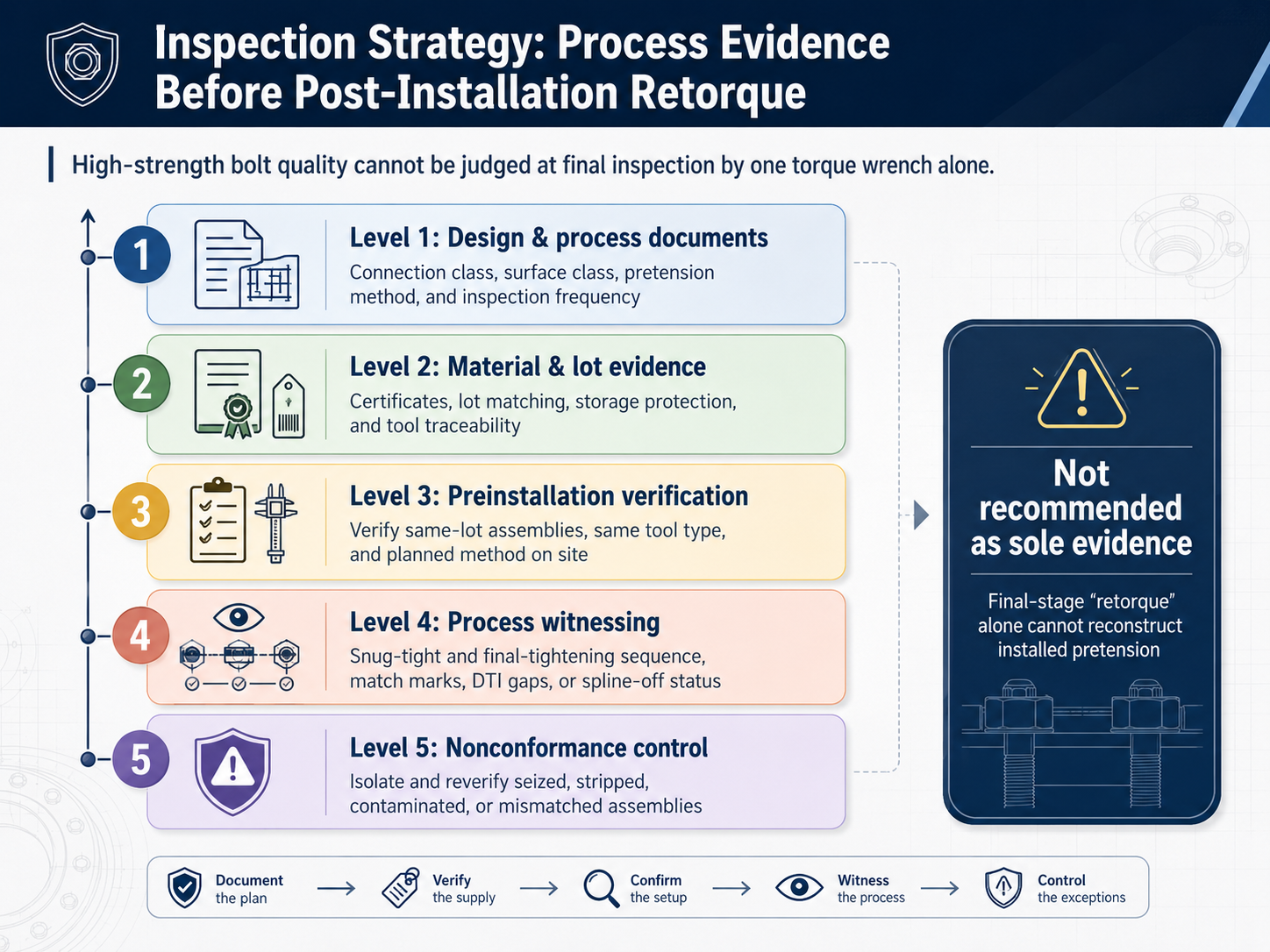
After high-strength bolts have been installed, many projects habitually apply a torque wrench to each nut and assume that no nut movement means adequate pretension. This practice cannot reliably reconstruct the actual installation pretension because static friction, thread condition, and surface changes over time all affect breakaway torque. RCSC specifically discusses the limitations of post-installation torque arbitration and emphasizes that inspectors should observe preinstallation verification, confirm the snug-tight condition, and routinely witness execution of the selected tightening method.[1]
An effective inspection record should form a chain of evidence: design documents define the connection category; material certificates establish assembly specifications; storage records confirm packaging and protection; faying-surface inspection confirms that the controlled zone is free of coating overspray, oil, and abnormal rusting; preinstallation verification demonstrates that the same-lot assemblies and tools can achieve the target pretension; process records show that the crew completed snug tightening and final tightening in the required sequence; and nonconformance reports show that seized, stripped-thread, mismatched, or contaminated assemblies were isolated.
For slip-critical connections, inspectors must also consider secondary work after assembly. Weld repair, touch-up painting, cutting, or grinding near the faying surfaces can reintroduce dust, paint, or heat effects into the connection zone. Leaving members outdoors for an extended period before final tightening can also change surface and thread conditions. A field sign-off should not merely state “bolts tightened”; it should certify that “the design-specified connection system was completed under the verified conditions.”
Quality problems in slip-critical connections are often not caused by one worker missing one turn. They arise because design, procurement, fabrication, and erection documents do not use the same language. The design notes specify a slip coefficient, but the purchase order lists only bolt grade; the shop drawing marks the faying surface, but the coating schedule omits the masking boundary; the erection procedure specifies the turn-of-nut method, but the field record provides only a “torque value” box. Each document may appear complete in isolation, yet the system does not close when they are combined.
The project should use a one-page “High-Strength Bolting Control Sheet” listing the joint number, connection category, hole type, faying-surface class or coating qualification, bolt-assembly standard, pretensioning method, preinstallation-verification frequency, process witness points, and final record name. Before members leave the shop, production personnel should check the faying surfaces and identification against the sheet; before shipment, the controlled zone should be sealed or covered; on site, the lot and packaging should be checked at receipt; verification should be completed before installation; and after final tightening, acceptance should be documented by match marks, DTI evidence, or the evidence required by the selected method.
The purpose of this special control sheet is not to create another form; it is to convert the vague concept of “high-strength bolting quality” into deliverable engineering objects. For steel-warehouse projects undertaken by Shenyang Zhongwei Heavy Industry Steel Structure Engineering Co., Ltd., high-strength bolted connections can be managed as an independent quality package: design parameters have stated sources, production surfaces have defined boundaries, assembly lots are traceable, field methods are verified, and inspection conclusions are evidence-based. Only then does the slip coefficient become more than a number in the calculation report; it becomes a connection performance that can function throughout the service life of the structure.
The reliability of a slip-critical connection is never determined by a “higher bolt grade” or a “larger torque value” alone. It rests on three interdependent conditions: the faying surfaces remain in the verified condition; the bolt assemblies develop sufficient and stable pretension; and the construction and inspection process demonstrates that both conditions were achieved at the same time.
For steel warehouses, the most economical approach is not extensive retightening after completion, but defining the control boundaries before fabrication and erection: manage faying surfaces separately, do not mix lots, verify tools first, use a witnessable method, and isolate abnormalities immediately. When these controls are performed early, a high-strength bolted connection advances from “appears tight” to “performance confirmed.”
No. |
Standard / Specification |
Purpose in This Article |
1 |
Research Council on Structural Connections (RCSC), Specification for Structural Joints Using High-Strength Bolts, June 11, 2020. |
Definitions of slip-critical joints; faying-surface conditions; preinstallation verification; tightening methods; inspection requirements. |
2 |
BS EN 1090-2:2018+A1:2024, Execution of steel structures and aluminium structures — Technical requirements for steel structures. |
Execution of steel structures; preparation of connection surfaces; assembly; tightening quality. |
3 |
ISO 16047:2005 + Amd 1:2012, Fasteners — Torque/clamp force testing. |
Test conditions for the torque–clamp-force relationship and the effect of friction. |
4 |
ANSI/AISC 360-22, Specification for Structural Steel Buildings (including applicable AISC errata). |
General requirements for structural-steel building design and connection design. |
5 |
ASTM F3125/F3125M-25, Standard Specification for High Strength Structural Bolts and Assemblies, Steel and Alloy Steel, Heat Treated. |
Material, mechanical-property, and product requirements for high-strength structural bolts and assemblies. |
6 |
ISO 898-1:2013 + Cor 1:2013, Mechanical properties of fasteners made of carbon steel and alloy steel — Part 1. |
Mechanical and physical property requirements for carbon- and alloy-steel bolts, screws, and studs. |
 EN
EN